Near-infrared two-region aggregation-induced emission molecule and application thereof
A molecular and rotor technology used in the field of near-infrared second region fluorescence imaging
- Summary
- Abstract
- Description
- Claims
- Application Information
AI Technical Summary
Problems solved by technology
Method used
Image

Examples
Embodiment 1
[0149] Example 1: Compound Synthesis
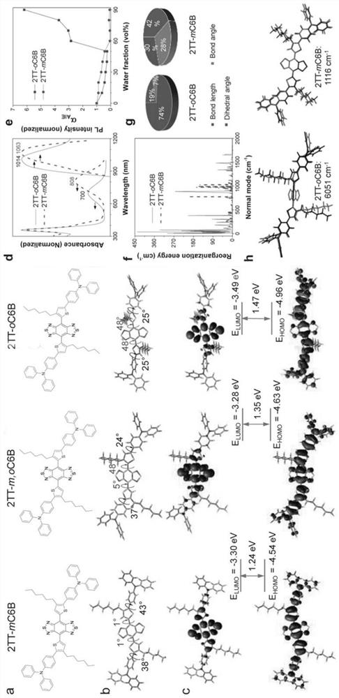
[0150] Synthetic roadmap of 2TT-oC6B:
[0151]
[0152] Synthesis of compound 2TT-oC6B
[0153] To synthesize compound 2TT-oC6B, to a 10 mL tube were added organotin (1, 0.7 g, 1 mmol), dibromo-BBT (2, 87 mg, 0.25 mmol), Pd 2 (dba) 3 (22mg, 0.025mmol), P(o-tol) 3 (66 mg, 0.21 mmol) and degassed dry toluene (1.5 mL) and sealed with a Teflon cap. in N 2 Under atmosphere, the reaction mixture was heated to 130°C with stirring for 48 hours. After cooling, the crude product was quenched with potassium fluoride (KF) solution, extracted with dichloromethane (DCM), and washed with Na 2 SO 4 The combined organic phases were dried. After removal of the solvent, the product was purified with a silica gel column to give a dark green solid (35% yield). 1 H NMR (400MHz, CDCl 3 ), δ(ppm)=7.59-7.56(4H,m), 7.37(2H,s), 7.31-7.26(8H,m), 7.16-7.12(8H,m), 7.11-7.03(8H,m), 2.61-2.57(4H,t,J=8Hz),1.63,(4H,m),1.15-1.10(12H,m),0.73(6H,m). 13 C NMR (...
Embodiment 2
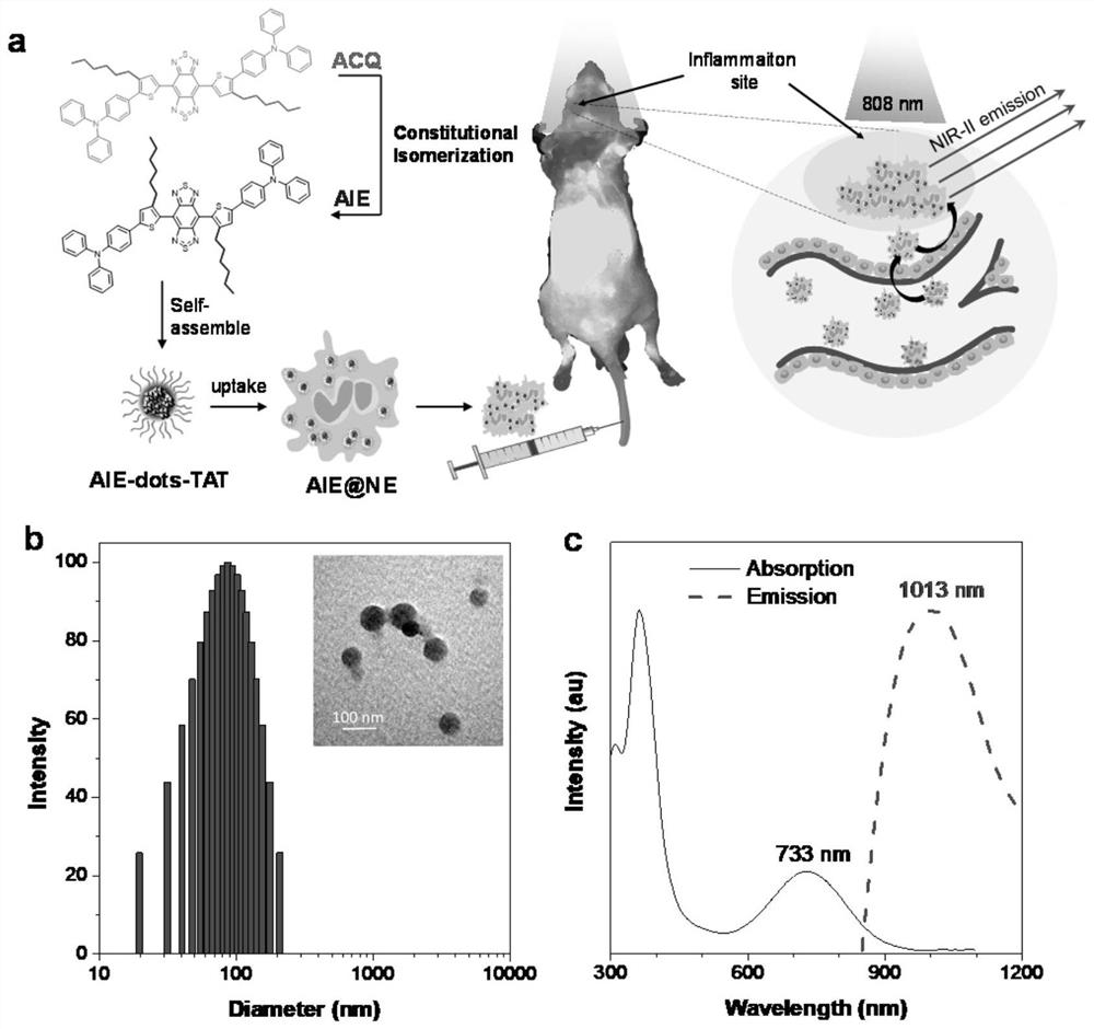
[0161] Example 2: Fabrication of AIE Nanoparticles (AIE-dot)
[0162] A mixture of compounds 2TT-oC6B, 2TT-mC6B or 2TT-m,oC6B (1 mg), DSPE-polyethylene glycol 2000-maleimide (1.5 mg) and tetrahydrofuran (THF) (1 mL) was sonicated ( 12W output, XL2000, Misonix Incorporated, NY) to obtain a clear solution. The solution was quickly poured into 9 mL of water and vigorously sonicated in the water for 2 minutes. The mixture was then stirred in a fume hood for 12 hours to remove THF. The AIE nanoparticle suspension was ultrafiltered (molecular weight cutoff 100 kDa) at 3000 xg for 30 minutes. It was found that compounds 2TT-oC6B, 2TT-mC6B or 2TT-m,oC6B were successfully encapsulated into DSPE-polyethylene glycol 2000-maleimide matrix in the form of AIE nanoparticles.
Embodiment 3
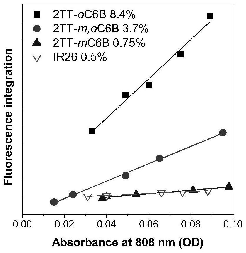
[0163] Example 3: Determination of Dye Fluorescence Quantum Yield (QY)
[0164] The QY of the dye was measured using the NIR-II type fluorescent IR-26 dye as a reference (QY=0.5%). For reference calibration, IR-26 in 1,2-dichloroethane (DCE) was diluted to a DCE solution to prepare five samples with absorbance values at 808 nm of ~0.1, ~0.08, ~0.06, ~0.04, and ~0.02 because these highly diluted samples minimize secondary optical processes such as reabsorption and reemission effects. Then, a total of five concentrations of linearly spaced solutions of IR-26 in DCE were transferred into 10 mm path fluorescent tubes at one time. The excitation source was an 808 nm diode laser. The emission light was filtered with a 900 nm long pass to exclude other light interference, and the emission spectrum in the 900 nm to 1500 nm region was acquired. For DCE and H 2 The same was done for AIE dyes in O. Then, all emission spectra of the reference and sample were integrated in the NIR-I...
PUM
| Property | Measurement | Unit |
|---|---|---|
| The average diameter | aaaaa | aaaaa |
| The average diameter | aaaaa | aaaaa |
Abstract
Description
Claims
Application Information
PatSnap Eureka turns technology decisions into work you can execute. Powered by our Innovation Knowledge Graph, it runs expert workflows across engineering, life sciences, materials and intellectual property. Get your review-ready output in minutes.


