
Circularly polarized microstrip antenna, OBU device and vehicle glass

A technology of microstrip antenna and vehicle glass, which is applied to antenna grounding device, antenna support/installation device, antenna and other directions, can solve the problems of affecting appearance, unsightly, affecting service life and performance, etc., and achieves integration, Simple structure design

Pending Publication Date: 2022-02-18
FUYAO GLASS IND GROUP
View PDF0 Cites 0 Cited by
  • Summary
  • Abstract
  • Description
  • Claims
  • Application Information

AI Technical Summary

Problems solved by technology

[0005] (1) The OBU is installed on the inner surface of the glass: it is difficult to avoid the influence of the glass on the antenna performance
Affect the appearance, you need to find a suitable position on the glass to install the OBU box
[0006] (2) The antenna part of the OBU is installed on the outer surface of the glass: although the influence of the glass on the performance of the antenna is avoided, the antenna will be affected by the external environment and easily corroded, thus affecting the service life and performance, and it is not beautiful
[0007] (3) Restricted by the material and thickness of the board, the front glass assembling process, etc., the existing OBU unit antenna technology cannot be separated from the box and directly sandwiched between the two pieces of glass
Therefore, the antenna and the vehicle glass are separated and not integrated

Method used


Image

  • Circularly polarized microstrip antenna, OBU device and vehicle glass
  • Circularly polarized microstrip antenna, OBU device and vehicle glass
  • Circularly polarized microstrip antenna, OBU device and vehicle glass

Examples


Embodiment 1

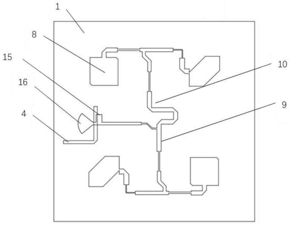
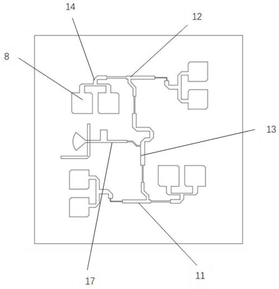
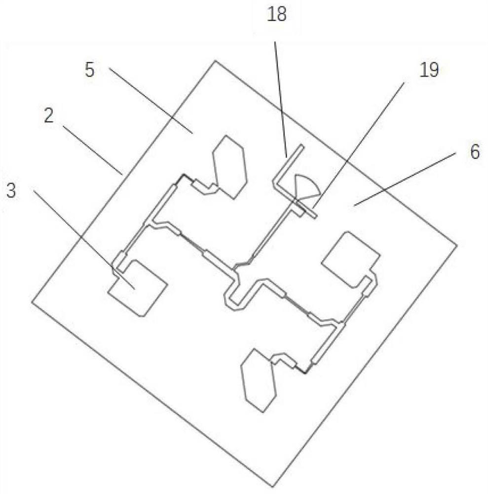
[0046] Such as Figure 1 ~ Figure 3 As shown, the present embodiment provides a circularly polarized microstrip antenna, including an insulating dielectric plate 1 and a grounding plate 2 arranged on the back side of the insulating dielectric plate 1, and a radiation layer 3 arranged on the front side of the insulating dielectric plate 1; the grounding plate 2 reflect the antenna signal and make the radiation direction outward; the size of the ground plate 2 is preferably 50mm×50mm; the ground plate 2 is provided with a slot 4, and the slot 4 divides the ground plate 2 into a first ground plate 5 and a second ground plate 5. Two grounding plates 6, the first grounding plate 5 and the second grounding plate 6 are electrically connected with the feed element 7 respectively, the setting of the slot groove 4 makes a potential difference between the first grounding plate 5 and the second grounding plate 6, that is, the The signal on the microstrip transmission line around the slot ...

Embodiment 2

[0051] Such as Figure 4 ~ Figure 6 As shown, the present application also provides an OBU device, including the above-mentioned circularly polarized microstrip antenna and an OBU control device, and the circularly polarized microstrip antenna is electrically connected to the OBU control device through a feeding element 7 . The circularly polarized microstrip antenna in the OBU device and the OBU control device can be connected separately through the feed element 7, so as to avoid being concentrated in the same OBU black box, which solves the problem of unsightly use and the need to find a suitable one on the vehicle glass. position to install the OBU box; where the feed element 7 is preferably a coaxial line 20, the coaxial line 20 includes an inner conductor 21, an outer conductor 22 and an insulating layer 23; the outer side of the inner conductor 21 is covered with an insulating layer 23, The insulating layer 23 is covered with an outer conductor 22 , and the outer conduct...

Embodiment 3

[0054] Such as Figure 7 As shown, the present application also provides a vehicle glass, including the circularly polarized microstrip antenna of Embodiment 1. The vehicle glass is laminated glass, including an inner layer glass 24, an intermediate layer 25 and an outer layer glass 26 stacked in sequence. The insulating dielectric plate 1 of the polarized microstrip antenna is an inner glass 24; the material of the middle layer 25 is preferably polyvinyl butyral (PVB), and polycarbonate (PC), sound-insulating PVB, light-shielding tape PVB, thermal Control PVB, ethylene vinyl acetate (EVA), thermoplastic polyurethane (TPU), ionomers, thermoplastics, polybutylene terephthalate (PBT), polyethylene vinyl acetate (PET), polyethylene naphthalate Ethylene glycol ester (PEN), polyvinyl chloride (PVC), polyvinyl fluoride (PVf), polyacrylate (PA), polymethyl methacrylate (PMMA), polyurethane (PUR) and their combinations, etc.

[0055] The radiation layer 3 of the circularly polarized ...


PUM

PropertyMeasurementUnit
Opening angleaaaaaaaaaa
Lengthaaaaaaaaaa
Widthaaaaaaaaaa

Abstract

The invention discloses a circularly polarized microstrip antenna, an OBU device and vehicle glass. The circularly polarized microstrip antenna comprises an insulating dielectric plate, a grounding plate arranged on the back surface of the insulating dielectric plate, and a radiation layer arranged on the front surface of the insulating dielectric plate; the grounding plate is provided with a slot, the slot divides the grounding plate into a first grounding plate and a second grounding plate, and the first grounding plate and the second grounding plate are respectively used for being electrically connected with a feed element; the slot is used for electrically connecting the radiation layer with the feed element; the OBU device comprises the circularly polarized microstrip antenna and an OBU control device, and the circularly polarized microstrip antenna is electrically connected with the OBU control device through a feed element. According to the circularly polarized microstrip antenna, the radiation layer and the slot are arranged, so that the circularly polarized microstrip antenna can be separated from a hardware circuit, and the circularly polarized microstrip antenna can be conveniently adapted to different use places; and the radiation layer is simple in structure, and industrialization is easy to realize.

Description

technical field [0001] The invention relates to the field of intelligent traffic equipment, in particular to a circularly polarized microstrip antenna, an OBU device and vehicle glass. Background technique [0002] ETC (Electronic Toll Collection) is a fully automatic electronic toll collection system, which is one of the service functions of the intelligent transportation system. It is especially suitable for toll points on expressways and roads and bridges. Car owners only need to install the ETC on-board unit (OBU) on the front windshield of the vehicle, and pre-store the fee, and then there is no need to manually pay the toll when passing the toll booth, and there is no need to stop. This charging system takes less than two seconds per vehicle, and the traffic capacity of the toll channel is 5 to 10 times that of the manual toll channel. [0003] In May 2019, the country accelerated the construction of ETC toll stations, and the future use of ETC reached more than 90%. ...

Claims


Application Information

Patent Timeline
IPC IPC(8): H01Q1/12H01Q1/36H01Q1/38H01Q1/48H01Q1/50H01Q13/08H01Q15/24
CPCH01Q1/1271H01Q1/36H01Q1/38H01Q1/48H01Q1/50H01Q13/08H01Q15/244
Inventor 武菲菲张火张丹群林勇王新全徐宁
Owner FUYAO GLASS IND GROUP
Learn More