
Rotary chemiluminescent protein chip

A chemiluminescence and protein chip technology, which is applied in chemiluminescence/bioluminescence, analysis through chemical reactions of materials, scientific instruments, etc., can solve the problem that liquid cannot be effectively removed, the repeatability of protein chips is not high, and infiltration Uncontrollable time and other issues, to achieve the effect of low assembly difficulty, improved repeatability, and simple structure

Pending Publication Date: 2022-04-05
TAIZHOU SYNO GENE DIGITAL TECH CO LTD
View PDF11 Cites 0 Cited by
  • Summary
  • Abstract
  • Description
  • Claims
  • Application Information

AI Technical Summary

Problems solved by technology

The filter-type protein chip improves the sensitivity and specificity of detection, but there are still some deficiencies in use. Specifically, it controls the movement of the piston through the pump and then controls the flow direction of the liquid. The infiltration time is still in an uncontrollable state, or the control accuracy is still unsatisfactory, and the liquid cannot be effectively removed during the reciprocating movement of the piston. The sample needs to be repeatedly filtered through the chip in the chip chamber, so draining is a relatively difficult task. The obvious problem is that the liquids used in each process will interfere with each other, the repeatability of this protein chip is not high, and the detection sensitivity needs to be further improved

Method used


Image

  • Rotary chemiluminescent protein chip
  • Rotary chemiluminescent protein chip
  • Rotary chemiluminescent protein chip

Examples


Embodiment 1

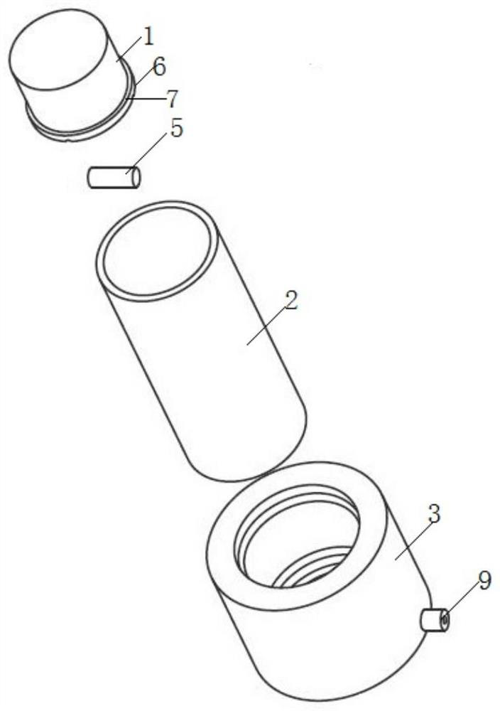
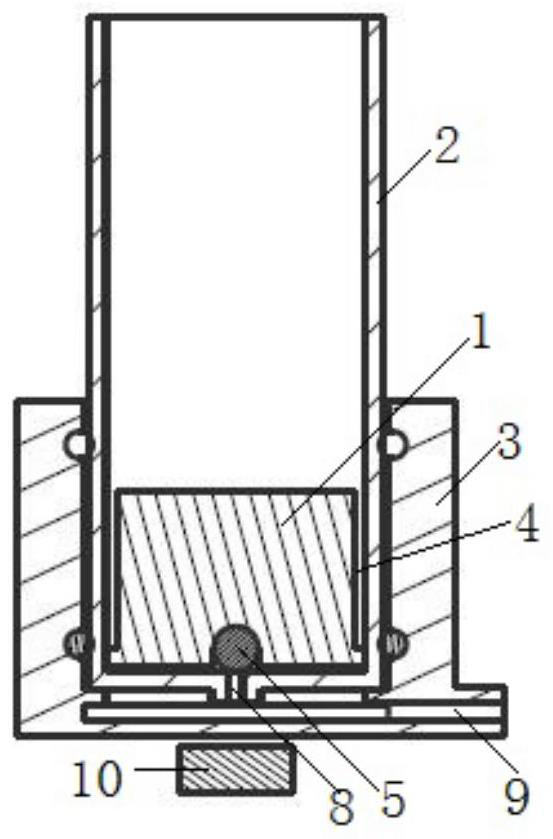
[0035] (1) Stick the porous carrier 4 coated with the Helicobacter pylori antigen microarray (nitrocellulose membrane is used as the carrier in this embodiment) to the outer ring of the cylindrical rotor 1 with self-adhesive or other adhesive film On the surface, the rotor 1 is placed in a cylindrical cuvette 2 made of transparent organic glass;

[0036] (2) Add 200 μL of the sample to be tested into the cuvette 2 at room temperature;

[0037] (3) Place the cuvette 2 on the base 3 and place the base 3 on the magnetic stirrer 10, turn on the magnetic stirrer 10, the reaction time is 10min, the rotating speed is 200r / min, the rotor 1 in the cuvette 2 starts to rotate , to drive the nitrocellulose diaphragm on the rotor 1 to rotate together;

[0038] (4) After the reaction is completed, the peristaltic pump is turned on, and the excess liquid in the cuvette 2 is sucked out by the peristaltic pump through the drain pipe 9 at the bottom of the cuvette 2;

[0039] (5) Add 300 μL o...


PUM


Abstract

The invention discloses a rotary chemiluminescent protein chip, which comprises a rotor, a reaction ring, a base and a porous carrier coated with an antigen or antibody microarray, the porous carrier is pasted on the peripheral ring surface of the rotor, the rotor is arranged in a reaction cup, a magnet is arranged in the rotor, a circle of ring edge is arranged on the periphery of the lower part of the rotor, and the ring edge is arranged on the base. The annular edge is connected with the rotor through a connecting rod at intervals, and the rotor and the annular edge define a vertically-through circular flow guide groove; a vertically through liquid leading-out hole is formed in the bottom surface of the reaction cup, and the reaction cup is arranged in the base; a drain pipe is arranged in a bottom panel of the base, one end of the drain pipe is communicated with the inside of the base, and the other end of the drain pipe is connected with a negative pressure pump. By improving the chip structure and under the assistance of magnetic stirring and pump suction, the detection repeatability can be improved by assisting high-efficiency reaction of each step, various liquids used in the detection process can be timely and orderly guided out, and the design and manufacturing requirements of products with higher repeatability requirements can be met.

Description

technical field [0001] The invention belongs to the technical field of immunobiology, and in particular relates to a rotary chemiluminescent protein chip. Background technique [0002] Microarray protein chip technology is a technology that immobilizes specific antigens and antibodies on the surface of a flat carrier in the form of a microarray, and uses the immunological reaction of antigens and antibodies for detection. The existing common technical scheme is to coat the antigen or antibody microarray on the planar carrier, place one or more layers of water-absorbing materials (paper fiberboard, cotton fiber, etc.) under the planar carrier, and then pack it into the chip housing; Add the sample to be tested on the surface of the chip, add the washing solution after the sample penetrates, add the enzyme-labeled antibody after the washing solution penetrates, add the washing solution after the enzyme-labeled antibody penetrates, and finally add the chromogenic substrate, and...

Claims


Application Information

Patent Timeline
IPC IPC(8): G01N21/76G01N21/01
Inventor 闫小君王小明潘宝华曾德隆阎平希
Owner TAIZHOU SYNO GENE DIGITAL TECH CO LTD
Learn More