Supercharge Your Innovation With Domain-Expert AI Agents!

Quenching and restoring circuit of silicon-based single-photon detector and control method of quenching and restoring circuit

A single-photon detector and recovery circuit technology, applied in the field of photodetectors, can solve problems such as large RC time constants that cannot be satisfied at the same time, low counting rate of silicon-based single-photon detectors, MOSFET damage, etc., to achieve short turn-on and turn-off time, low quiescent power consumption, and the effect of fast switching speed

Pending Publication Date: 2022-04-12
THE 44TH INST OF CHINA ELECTRONICS TECH GROUP CORP
View PDF0 Cites 0 Cited by
  • Summary
  • Abstract
  • Description
  • Claims
  • Application Information

AI Technical Summary

Problems solved by technology

[0006] In view of this, the object of the present invention is to provide a silicon-based single photon detector quenching and recovery circuit and its control method to solve the problem of resistance due to high and low voltage switching by connecting pull-up or pull-down resistors in the prior art. Too small, a large voltage drop forms a transient large current, resulting in high power consumption and damage to the MOSFET, or due to excessive resistance, the RC time constant cannot meet the overbias voltage at the same time. Short turn-on time and short turn-off time lead to silicon-based single-photon detection The problem of low counter count rate

Method used


Image

  • Quenching and restoring circuit of silicon-based single-photon detector and control method of quenching and restoring circuit
  • Quenching and restoring circuit of silicon-based single-photon detector and control method of quenching and restoring circuit
  • Quenching and restoring circuit of silicon-based single-photon detector and control method of quenching and restoring circuit

Examples


Embodiment 1

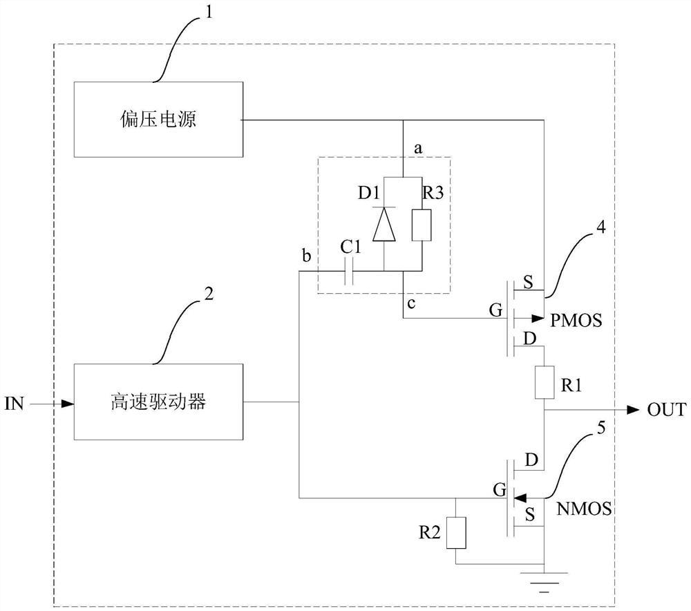
[0035] Such as figure 1 As shown, it is a schematic circuit diagram of a quenching and recovery circuit of a silicon-based single photon detector in this embodiment. The quenching and recovery circuit of the silicon-based single-photon detector in this embodiment is used to generate a large voltage pulse signal with a high voltage amplitude. The silicon-based single-photon detector has a total input terminal IN and a total output terminal OUT, so The total input terminal IN is used to receive a preset pulse, and the total output terminal OUT is used to provide the large voltage pulse signal to improve the detection efficiency of the silicon-based single photon detector.

[0036] The quenching and recovery circuit of the silicon-based single photon detector of this embodiment includes a bias power supply 1 , a high-speed driver 2 , a negative deviation clamping sub-circuit 3 , a PMOS transistor 4 and an NMOS transistor 5 . Specifically, the input terminal of the high-speed dri...

Embodiment 2

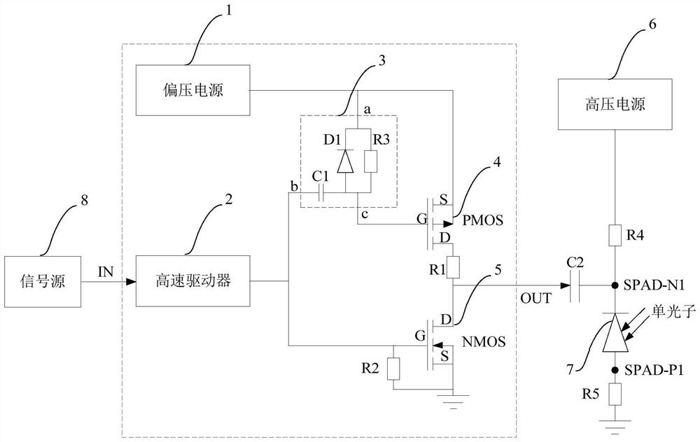
[0043] Such as figure 2 As shown, it is a circuit schematic diagram of a silicon-based single photon quenching and recovery circuit in the embodiment of this city. This embodiment includes a bias power supply 1 , a high-speed driver 2 , a negative deviation clamping sub-circuit 3 , a PMOS transistor 4 and an NMOS transistor 5 with the same or similar structure and function as that of the first embodiment. The difference of this embodiment is that the silicon-based single-photon quenching and recovery circuit of this embodiment is mainly used for quenching the avalanche signal and restoring the bias voltage of the silicon-based single-photon detector in the gating mode. details as follows:

[0044] This embodiment also includes a high voltage power supply 6, a fourth resistor R4, a silicon-based single photon detector 7, a signal source 8 and a second capacitor C2. Specifically, the output end of the high-voltage power supply 6 is electrically connected to the N pole of the ...

Embodiment 3

[0048] Such as Figure 4 Shown is a circuit schematic diagram of a silicon-based single-photon quenching and recovery circuit of this embodiment. This embodiment includes a bias power supply 1 , a high-speed driver 2 , a negative deviation clamping sub-circuit 3 , a PMOS transistor 4 and an NMOS transistor 5 with the same or similar structure and function as that of the first embodiment. The difference of this embodiment is that the silicon-based single-photon quenching and recovery circuit of this embodiment is mainly used for quenching the avalanche signal and recovering the bias voltage of the silicon-based single-photon detector in active mode. details as follows:

[0049] This embodiment also includes a high voltage power supply 6, a fourth resistor R4, a silicon-based single photon detector 7, an avalanche signal detection and feedback sub-circuit 9 and a third capacitor C3. Specifically, the output end of the high-voltage power supply 6 is electrically connected to th...


PUM


Abstract

The invention discloses a quenching and restoring circuit of a silicon-based single-photon detector and a control method of the quenching and restoring circuit, the quenching and restoring circuit of the silicon-based single-photon detector is provided with a total input end and a total output end, and the quenching and restoring circuit of the silicon-based single-photon detector comprises a bias power supply, a high-speed driver, a negative deviation clamping sub-circuit, a PMOS (P-channel Metal Oxide Semiconductor) tube and an NMOS (N-channel Metal Oxide Semiconductor) tube, a large voltage pulse signal can be generated at the total output end to improve the detection efficiency of the silicon-based single-photon detector, and the NMOS tube and the PMOS tube alternately work, so that the whole quenching and restoring circuit has low static power consumption, the service life is prolonged, and the cost is reduced. And the obtained higher switching speed and shorter turn-on and turn-off time are beneficial to reducing dark counting and detecting dead zone time and improving the counting rate of the silicon-based single-photon detector, so that the method can be suitable for quenching and recovery of the silicon-based single-photon detector in a gating mode and an active mode, and is higher in universality.

Description

technical field [0001] The invention relates to the technical field of photoelectric detectors, and specifically discloses a silicon-based single-photon detector quenching and recovery circuit and a control method thereof. Background technique [0002] Compared with InGaAs single-photon detectors, silicon single-photon detectors have the advantages of low dark count rate and short detection dead time, but the device structure and the technology adopted determine the breakdown voltage V of near-infrared silicon single-photon detectors. BR As many as hundreds of thousands of volts, which also means that to achieve high near-infrared single-photon detection efficiency, a voltage tens of volts higher than the breakdown voltage needs to be added. but continues to increase well above the device breakdown voltage V BR The continuous high power consumption of the device can easily lead to damage to the device. Therefore, single-photon detectors need to be combined with correspondi...

Claims


Application Information

Patent Timeline
IPC IPC(8): H03K17/687H03K17/042G01J11/00
Inventor 唐遵烈马华平邓光平郭安然黄建张洪博
Owner THE 44TH INST OF CHINA ELECTRONICS TECH GROUP CORP
Features
  • R&D
  • Intellectual Property
  • Life Sciences
  • Materials
  • Tech Scout
  • Unparalleled Data Quality
  • Higher Quality Content
  • 60% Fewer Hallucinations
Learn More