Petrochemical enterprise oily sludge deoiling treatment method

A petrochemical and oil treatment technology, applied in sludge treatment, water/sludge/sewage treatment, sludge treatment by temperature control, etc. High problems, to achieve the effect of increasing spontaneous combustion, improving sludge drying conditions, and reducing sludge oil content

Inactive Publication Date: 2022-05-10
CHINA PETROLEUM & CHEM CORP +2
View PDF3 Cites 0 Cited by
  • Summary
  • Abstract
  • Description
  • Claims
  • Application Information

AI Technical Summary

Problems solved by technology

However, since most of the dirty oil is still carried by the sludge after the initial degreasing, it is not removed from the sludge, and only free oil is removed by dehydration, and the oil content of the sludge is still very high
In addition, when the separated waste oil is mixed with activated sludge for dehydration, it is absorbed by the activated sludge with a very low oil content, which increases the oil content of the dried sludge as a whole, seriously restricting the use of sludge drying equipment

Method used


Image

  • Petrochemical enterprise oily sludge deoiling treatment method
  • Petrochemical enterprise oily sludge deoiling treatment method

Examples


Embodiment 1

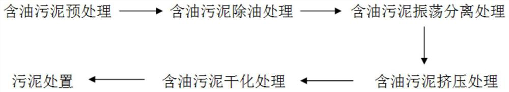
[0031] Oily sludge is hazardous waste, and activated sludge is general waste. The mixed treatment of oily sludge and activated sludge will affect the disposal method and cost of dried sludge. Therefore, oily sludge should be dried and disposed of separately. . Its treatment methods include:

[0032] The oily sludge in petrochemical enterprises is lifted by the system sludge lifting pump, and then sent to the oily sludge degreasing device for degreasing treatment, and the discharged sewage is used for oil recovery. The oily sludge after degreasing treatment enters the extrusion dehydrator for extrusion dehydration treatment alone, and the discharged sewage is treated together with the sewage discharged from the oily sludge degreasing device for waste oil recovery treatment. The oily sludge after extrusion dehydration is sent to the drying machine for drying treatment, and the sludge after drying treatment is disposed of separately. Its detailed production steps are:

[0033]...

Embodiment 2

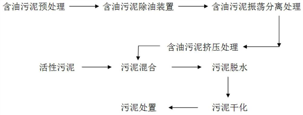
[0055] The oily sludge after degreasing and extrusion is mixed with activated sludge and sent to the enterprise incinerator or power station for incineration, which does not affect the disposal method and cost of dried sludge. Its treatment methods include:

[0056] The oily sludge in petrochemical enterprises is lifted by the system sludge lifting pump, and then sent to the oily sludge degreasing device for degreasing treatment, and the discharged sewage is used for oil recovery. The oily sludge after oil removal treatment enters the extrusion treatment for extrusion treatment alone, and the discharged sewage is treated together with the sewage discharged from the oily sludge degreasing device for waste oil recovery treatment. The oily sludge after extrusion treatment is sent to the oily sludge and activated sludge mixing facility for mixing conditioning treatment, and after being lifted, it is sent to the sludge dewatering machine for dehydration treatment. The mixed sludge...


PUM

PropertyMeasurementUnit
particle sizeaaaaaaaaaa

Abstract

The invention provides an oil removal treatment method for oily sludge of petrochemical enterprises. The oil removal treatment method comprises the following steps: carrying out heating and cutting pretreatment on the oily sludge of the enterprises; after being lifted by a system sludge lifting pump, the pretreated sludge is fed into an oil-containing sludge oil removal device for oil removal treatment; carrying out oscillation separation treatment on the sludge subjected to oil removal, and enabling oil-containing sludge to enter an oscillation separation tank; independently feeding the oil-containing sludge subjected to oscillation separation into extrusion equipment for extrusion treatment; independently drying and discharging the extruded oily sludge; or mixing with activated sludge, tempering, dehydrating, drying and then treating. According to the invention, the operation mode and design parameters are optimized, the investment and operation cost is reduced, the pollutant discharge is reduced, and the requirements of oily sludge drying feeding of petrochemical enterprises are met.

Description

technical field [0001] The invention belongs to the technical field of oily sludge treatment, and in particular relates to a method for oil removal treatment of oily sludge in petrochemical enterprises. Background technique [0002] With the development of our country's economy, the requirements for environmental protection are constantly increasing, and higher requirements are put forward for the sludge treatment of petrochemical enterprises: first, energy saving, energy consumption reduction, and stable operation; second, environmental protection and the reduction of sludge production as much as possible; The third is to keep it simple and minimize the land occupation. Failure to take measures against the above requirements will seriously restrict the development of enterprises. Therefore, adopting a new oily sludge degreasing technology in petrochemical enterprises can greatly reduce the amount of slagging in refining and chemical enterprises, especially the amount of sl...

Claims


Application Information

Patent Timeline
Patent Type & Authority Applications(China)
IPC IPC(8): C02F11/00C02F11/121C02F11/14C02F11/18C02F103/36
CPCC02F11/00C02F11/121C02F11/14C02F11/18C02F2103/365C02F2303/06
Inventor 滕宗礼胡建东王瑞珂蔺伟
Owner CHINA PETROLEUM & CHEM CORP
Why Eureka
Try Eureka