Single-fiber vortex optical tweezers and manufacturing method and modulation method thereof

A production method and vortex light technology, applied in the field of optical tweezers, can solve the problems of inability to achieve four-dimensional over-control, and the inability of fiber optical tweezers to fully meet new requirements, and achieve the effects of simple and easy operation, cost, and strong focusing effect.

Pending Publication Date: 2022-05-13
SHENZHEN UNIV
View PDF4 Cites 0 Cited by
  • Summary
  • Abstract
  • Description
  • Claims
  • Application Information

AI Technical Summary

Problems solved by technology

Single-fiber optical tweezers have realized the three-dimensional stable capture and manipulation of single particles, but single-fiber optical tweezers cannot re...

Method used


Image

  • Single-fiber vortex optical tweezers and manufacturing method and modulation method thereof
  • Single-fiber vortex optical tweezers and manufacturing method and modulation method thereof
  • Single-fiber vortex optical tweezers and manufacturing method and modulation method thereof

Examples


Embodiment 1

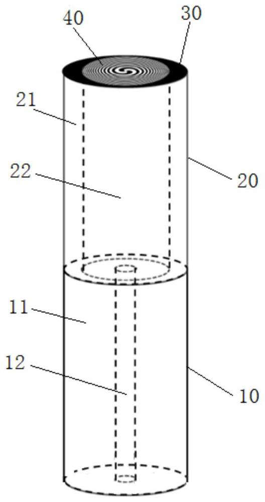
[0057] A specific embodiment of the present application provides a single-fiber vortex optical tweezers for etching a helical zone plate 40 on an optical fiber end face.

[0058] Such as figure 1 As shown, the single-fiber vortex optical tweezers include a single-mode fiber 10 and a graded-index multimode fiber 20 . Single-mode fiber, English name Single Mode Fiber, referred to as SMF. Graded Index Fiber, English name Graded IndexFiber, referred to as GIF. Wherein, one end of the single-mode optical fiber 10 is directly fused with the graded-index multimode optical fiber 20 to form a combined single-fiber vortex optical tweezers. There is a light-shielding film layer 30 on the fiber end face of the graded-index multimode fiber 20 ; the helical zone plate 40 is formed on the light-shielding film layer 30 . The spiral zone plate 40 forms a light-transmitting bright zone and an opaque dark zone on the light-shielding film layer 30 .

[0059] In this application, the single-mo...

Embodiment 2

[0092] A specific embodiment of the present application provides a method for manufacturing a single-fiber vortex optical tweezers for etching a spiral zone plate 40 on the end face of an optical fiber described in Embodiment 1, including the following steps:

[0093] S1, splicing a section of graded-index multimode optical fiber 20 at the end of the single-mode optical fiber 10;

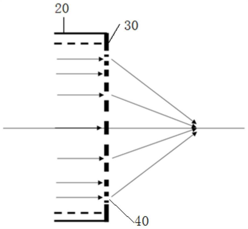
[0094] S2, prepare a spiral zone plate formed by a light-shielding film layer on the fiber end face of the graded-index multimode optical fiber 20, and the spiral zone plate 40 forms a light-transmitting bright wave zone and an opaque wave zone on the light-shielding film layer 30 dark band.

[0095] In step S1, the single-mode fiber 10 and the graded-index multimode fiber 20 can be spliced ​​by a fiber fusion splicer first, and then the graded-index multimode fiber 20 is cut to a corresponding required length by a fiber precision cutter. The precision cutting system consists of an optical fiber cu...

Embodiment 3

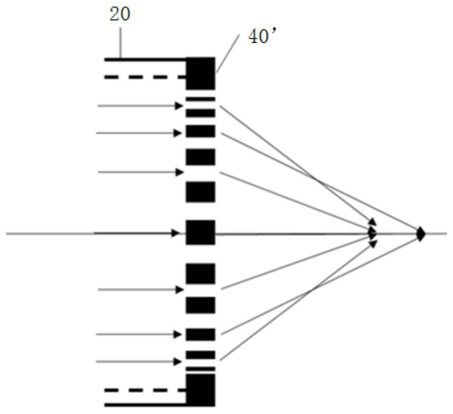
[0123] A specific embodiment of the present application provides a single-fiber vortex optical tweezers modulation technology, and the single-fiber vortex optical tweezers are as described above. Light with different wavelengths is input at the end of the single-mode optical fiber 10, and the axial capture of particles is controlled by controlling the wavelength of the incident light, so that the position of the focused light field can be adjusted in the axial direction.

[0124] Since the primary diffraction point is uniquely determined, according to the design principle of the helical zone plate 40, when the size of the helical zone plate 40 is fixed, the focal length of the focused light field obtained will change when the optical fiber inputs different wavelengths, and the wavelength The longer the focal length is, the shorter the focal length is, and the focus of the beam is closer to the end face of the fiber; on the contrary, when the wavelength of the incident light dec...


PUM

PropertyMeasurementUnit
Thicknessaaaaaaaaaa
Thicknessaaaaaaaaaa

Abstract

The invention provides a pair of single-fiber vortex optical tweezers, and a manufacturing method and a modulation method thereof. A section of gradient refractive index multimode optical fiber is welded at the end part of a single-mode optical fiber; a spiral wave zone plate formed by a shading film layer is prepared on the optical fiber end face of the multimode optical fiber with the gradient refractive index, and a light-transmitting bright wave zone and a light-proof dark wave zone are formed on the shading film layer by the spiral wave zone plate. The gradient refractive index multimode optical fiber can realize a larger beam expanding effect; the spiral wave zone plate enables light emitted from the end face of the optical fiber to pass through the spiral wave zone plate and realize vortex focusing behind the end face of the optical fiber; the dark wave zone is light-proof, only the bright wave zone is light-transmitting, and the spiral wave zone plate has only one primary diffraction focus all the time even in an environment with a changing refractive index. The single-fiber vortex optical tweezers not only can detect an emergent light field in an air environment and capture particles in a liquid environment, but also can change the axial position of the light trap by adjusting the wavelength of incident light, so that the particles are driven to axially move and rotate in fluid.

Description

technical field [0001] The invention relates to the technical field of optical tweezers, in particular to a single optical fiber vortex optical tweezers, a manufacturing method and a modulation method thereof. Background technique [0002] The structure of optical tweezers generally includes traditional lens group optical tweezers, flat end-face optical fiber optical tweezers, and tapered (hemispherical) self-lens end-face optical fiber optical tweezers. [0003] In the traditional lens group optical tweezers, the laser beam enters the microscope system after passing through the beam expander and the light intensity adjuster, and then is converged by the high-magnification microscope objective lens to form an optical trap, which controls the spatial distribution of tiny particles through the gradient field. The optical path of traditional optical tweezers constructed by this kind of spatial light is complex, the overall system is bulky, and it is difficult to control the fre...

Claims


Application Information

Patent Timeline
IPC IPC(8): G02B6/02G02B6/028G02B5/20G02B6/255G21K1/00
CPCG02B6/02047G02B6/0288G02B5/20G02B6/255G21K1/00
Inventor 白志勇吴璐平刘锐余建王义平
Owner SHENZHEN UNIV
Why Eureka
Try Eureka