
Bone-ligament-bone integrated stent and preparation method thereof

A technology of bone scaffold and ligament, which is applied in the field of bone-ligament-bone integrated scaffold and its preparation, can solve the problems of simultaneous repair of ligament and bone in the joint cavity, and achieve the advantages of cell ingrowth, strong mechanical properties, The effect of promoting bone healing

Active Publication Date: 2022-05-17
DONGHUA UNIV
View PDF7 Cites 1 Cited by
  • Summary
  • Abstract
  • Description
  • Claims
  • Application Information

AI Technical Summary

Problems solved by technology

[0006] The technical problem to be solved by the present invention is to provide a bone-ligament-bone integrated bracket and its preparation method to overcome the defect that the artificial ligament bracket in the prior art cannot realize the simultaneous repair of the ligament and bone in the joint cavity

Method used


Image

  • Bone-ligament-bone integrated stent and preparation method thereof
  • Bone-ligament-bone integrated stent and preparation method thereof
  • Bone-ligament-bone integrated stent and preparation method thereof

Examples


Embodiment 1

[0060] In this example, the silk fibroin thread (100-200 μm in diameter; Shanghai Tongjieliang Biomaterials Co., Ltd.) is used as the core layer of the nanofiber yarn, and the spinning solution is prepared by blending the polymer PLCL and the connective tissue growth factor CTGF , using mesoporous hydroxyapatite (MHA) to support deferoxamine (DFO) and polymer PLA to form a phase separation solution. Concrete preparation process is as follows:

[0061] S1: Preparation of spinning solution: prepare CTGF (PeproTech, USA) solution with a concentration of 2 μg / mL in phosphate buffer, accurately measure 10 mL of dichloromethane (purchased from Sinopharm Chemical Reagent Co., Ltd.) in a glass bottle, At the same time, 0.1 mL of Span 80 (purchased from Aladdin Biochemical Technology Co., Ltd.) and 0.5 mL of CTGF solution were added dropwise to the dichloromethane solution, then stirred at high speed for 12 h, and finally 1.0 g of PLCL (M w =80000, Jinan Daigang Biotechnology Co., Ltd...

Embodiment 2

[0082] In this example, PLA wires are used as the core layer of nanofiber yarns, the high molecular polymer PCL is used to prepare the spinning solution, and silicon dioxide and poly(lactic-co-glycolic acid) (PLGA) are used to form a phase-separated solution. Concrete preparation process is as follows:

[0083] S1: Preparation of spinning solution: accurately weigh 1.0g PCL (M w =100000, Shenzhen Guanghua Weiye Co., Ltd.) was dissolved in 10mL hexafluoroisopropanol (purchased in Shanghai Darui Fine Chemicals Co., Ltd.), stirred overnight, and was made into a PCL spinning solution with a mass volume concentration of 0.1g / mL .

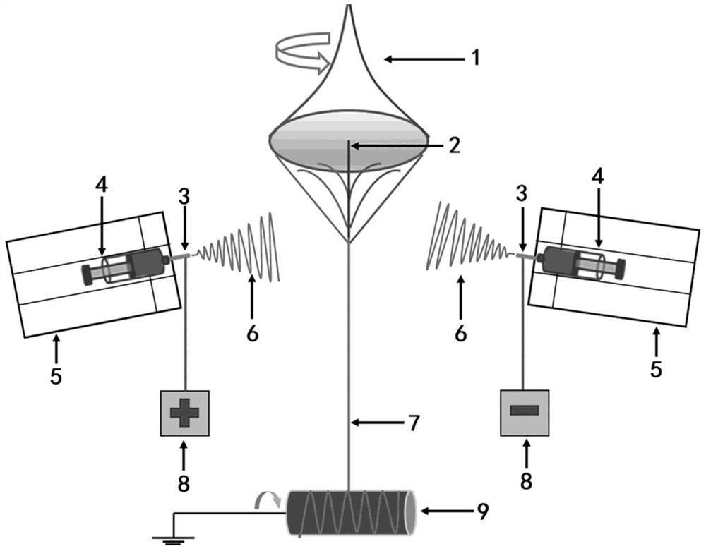
[0084] S2: Preparation of nanofiber yarn: as figure 1 As shown, the PLA thread 2 (50-100 μm in diameter; Shanghai Tongjieliang Biomaterials Co., Ltd.) was passed through the middle rotating funnel 1 of the multifunctional electrospinning machine as the core layer, and 10 mL of the spinning solution in S1 was transferred to Among the two counter-jet i...


PUM

PropertyMeasurementUnit
lengthaaaaaaaaaa
lengthaaaaaaaaaa
diameteraaaaaaaaaa

Abstract

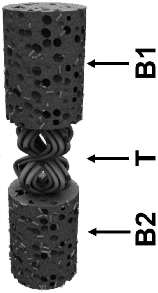
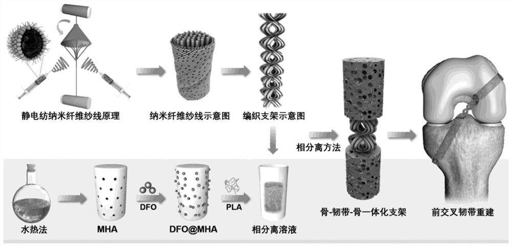
The invention relates to a bone-ligament-bone integrated stent and a preparation method thereof. The integrated stent is of a three-section structure and comprises bone stent parts at the two ends and a ligament stent part at the middle section, the ligament stent part at the middle section is an articular cavity nanofiber yarn woven section, and the bone stent parts are separated stent sections. The preparation method comprises the following steps: dissolving a degradable synthetic polymer or a natural high-molecular substance in a solvent to obtain a spinning solution, transferring the spinning solution to an injector, performing conjugate electrostatic spinning, twisting to the surface of a polymer line to obtain nanofiber yarns, weaving, respectively placing two ends of the obtained macroporous scaffold in a mold, then adding a phase separation solution into the mold, and carrying out phase separation to obtain the porous scaffold. And freezing and freeze-drying. After the stent is implanted, ligament tissue regeneration is guided in an articular cavity, bone tunnel healing is promoted in a bone tunnel, and the problem of bone tunnel expansion is solved.

Description

technical field [0001] The invention belongs to the field of biomedical materials and their preparation, in particular to a bone-ligament-bone integrated bracket and a preparation method thereof. Background technique [0002] Human ligaments are white band-shaped connective tissues that are tough and elastic, and can connect bones together and strengthen the stability of bones. Injury occurs when a ligament is stretched beyond its tolerance due to non-physiological activity caused by violence. Ligament injuries are mainly caused by strenuous exercise and external force factors, including fracture, tear, degeneration or inflammation, and have become one of the most common injuries in the human body. In addition, the knee joint is one of the most vulnerable joints in the human body. The stability of the knee joint is mainly maintained by a series of structures inside and outside the knee joint, including bony structures, extra-articular structures and intra-articular structur...

Claims


Application Information

Patent Timeline
Patent Type & Authority Applications(China)
IPC IPC(8): A61L27/18A61L27/02A61L27/12A61L27/20A61L27/22A61L27/24A61L27/54A61L27/58A61F2/38D04C1/02D04C1/06
CPCA61L27/18A61L27/20A61L27/222A61L27/24A61L27/227A61L27/025A61L27/12A61L27/58A61L27/54A61F2/38D04C1/02D04C1/06A61L2430/02A61L2430/34
Inventor 莫秀梅谢宪瑞
Owner DONGHUA UNIV
Learn More