
RF Particle Energy Focusing Clock Distribution Method for RF Particle Knife

A clock distribution and particle technology, which is applied in the parts of surgical instruments, medical science, surgery, etc., can solve the problems of prolonging the healing time of surgical incisions, poor safety performance of negative plates, and tissue extrusion, and achieves convenient waveform debugging. , The sampling frequency is easy to adjust, and the temperature drift is small.

Active Publication Date: 2022-07-08
天津苏德科技发展有限公司
View PDF0 Cites 0 Cited by
  • Summary
  • Abstract
  • Description
  • Claims
  • Application Information

AI Technical Summary

Problems solved by technology

Because it uses the current loop formed by the negative plate, the high-frequency current returns to the machine through the negative plate with the human body as the conductor, so it is very easy to cause defects and deficiencies: 1. The safety performance of the negative plate of the high-frequency electric knife is not good, If the speed is too fast and the force is too strong when removing the negative plate, mechanical damage such as separation of the epidermis and dermis or exfoliation of the epidermis may occur; Causes soft tissue damage, which can easily prolong the healing time of the surgical incision; 3. The high-frequency electric knife cannot perform unipolar brain surgery, cardiac ablation, spinal surgery and other operations
[0003] The Chinese utility model patent publication number is (CN 210250054 U) radio frequency particle knife, which discloses that when radio frequency radio waves are received by radio frequency energy recovery antennas to form a loop, the energy carried by radio frequency radio waves during transmission is concentrated at the end of radio frequency electrodes , so that the skin effect phenomenon is formed at the end of the radio frequency electrode, and it can be cut without resistance, and the minimum tissue damage and cell change are realized. Small focusing radius and focusing all RF particle energy on one point is still a difficult problem to solve

Method used


Image

  • RF Particle Energy Focusing Clock Distribution Method for RF Particle Knife
  • RF Particle Energy Focusing Clock Distribution Method for RF Particle Knife
  • RF Particle Energy Focusing Clock Distribution Method for RF Particle Knife

Examples


Embodiment 1

[0043] see Figure 1-6 , the present invention provides a technical solution: a radio frequency particle energy focusing clock distribution method for a radio frequency particle knife, comprising the following steps:

[0044] In step S1, according to the force of the radio frequency particles in the electric field and the magnetic field, a parameter model of the energy focusing of the radio frequency particles is constructed, and the factors affecting the energy focusing of the radio frequency particles are calculated as follows: the initial velocity of the radio frequency particles is parallel to the longitudinal component vector of the magnetic induction intensity. .

[0045] The specific process of constructing the parametric model of RF particle energy focusing is as follows:

[0046] Step S11, if the electric field strength of the electric field midpoint P is E, then the electric field force F on the radio frequency particle with the charge at this point is +q e for: F ...

Embodiment 2

[0064] The difference between this embodiment and Embodiment 1 is that the sampling frequency ADCCLK of the current carrying capacity collector is: ADCCLK=system clock / 4. When the system clock is 168MHz, the sampling frequency of the ampacity collector is 42MHz.

Embodiment 3

[0066] The difference between this embodiment and Embodiment 1 is that the clock source is selected as the external clock of ±5ppm crystal oscillator, when the system clock is 168MHz, then Fpwm=500000Hz, FAHB=168000000Hz, when pscX is set to 0, through arrX =FAHB / [Fpwm*(pscX+1)]-1 formula, get arrX=335, configure it to the waveform generator, and output the PWM waveform.

[0067] Select FAHB=168MHz, Tout=5us, according to the formula 2Tout=1 / f, the frequency f of the carrier is calculated to be 100KHz, according to the formula Tout =[(arr2+1)*(psc2+1)] / FAHB, the period register is calculated The value of TIM2_ARR is arr2=209. Therefore, the value of the configuration period register TIM2_ARR is 209, and a carrier with a frequency of 100 KHz is generated by the overflow interrupt of the general timer TIM2.


PUM


Abstract

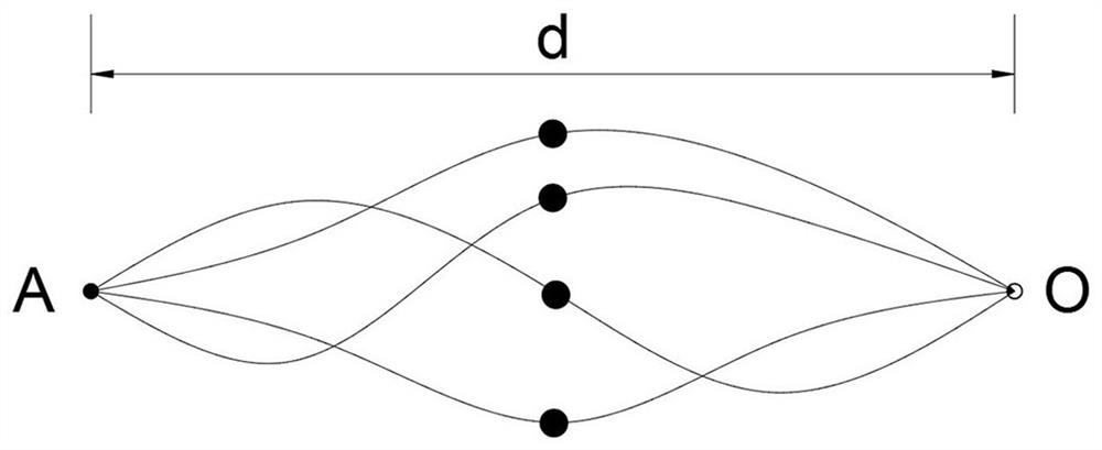
The invention discloses a radio frequency particle energy focusing clock distribution method for a radio frequency particle knife. The radio frequency particle energy focusing clock distribution system sends out an electrocoagulation waveform to make the initial velocity of each beam of radio frequency particles equal to the longitudinal vector of the initial velocity parallel to the magnetic induction intensity. , that is, let the pitches of all the radio frequency particles in this beam of radio frequency particles be equal. After this beam of radio frequency particles is emitted from a certain point A of the uniform magnetic field around the electrode, it intersects with the same point O after the same pitch, and point O is the radio frequency particle. The front end of the output electrode of the knife, so that a beam of radio frequency particle energy emitted by the radio frequency particle knife is focused, and the focused energy directly excites the liquid polar molecules in the tissue to generate plasma oscillations, breaking and dehydrating the molecular bonds of human or animal tissue. So as to achieve the effect of wireless cutting and electrocoagulation on the human body or animal body. The invention has low manufacturing cost, convenient waveform debugging, and the waveform frequency does not change with temperature.

Description

technical field [0001] The invention relates to the technical field of electrosurgical knives, in particular to a radio frequency particle energy focusing clock distribution method for radio frequency particle knives. Background technique [0002] Electrosurgery has a history of more than 70 years since its clinical application in 1920. At present, domestic electrosurgical scalpels are mainly high-frequency electrosurgery, with a frequency range of about 300-600KHZ. The tissue is heated to achieve separation and coagulation of the body tissue for the purpose of cutting and hemostasis. Widely used in general surgery, neurosurgery, microsurgery, thoracic surgery, orthopedics, gynecology, urology, ENT, plastic surgery and other surgical and endoscopic surgery. Since it uses a current loop composed of a negative plate, the high-frequency current takes the human body as a conductor to return to the machine through the negative plate, so it is very easy to cause defects and defi...

Claims


Application Information

Patent Timeline
Patent Type & Authority Patents(China)
IPC IPC(8): A61B18/12A61B18/14
CPCA61B18/12A61B18/1206A61B18/14A61B2018/1412A61B2018/00589A61B2018/00601A61B2018/00702A61B2018/00642A61B2018/00988
Inventor 王小明王喆
Owner 天津苏德科技发展有限公司
Learn More