Optical pulse time stretching device and method and spectral measurement system

A time-stretching, optical pulse technology, applied in the field of optical measurement, can solve the problems of reduced signal-to-noise ratio, large energy loss, etc., to achieve the effect of less energy loss, increase the number of small pulses, and improve the signal-to-noise ratio

Active Publication Date: 2022-06-24
SUN YAT SEN UNIV
View PDF8 Cites 0 Cited by
  • Summary
  • Abstract
  • Description
  • Claims
  • Application Information

AI Technical Summary

Problems solved by technology

[0005] The present invention provides an optical pulse time-stretching system, which is used to solve the problem that the amplitude of the optical pulse varies with the time-stretching of the optical pulse in the prior art. The increase of the amount of dispersion decreases, and there is a large energy loss, which leads to the technical problem of reducing the signal-to-noise ratio

Method used


Image

  • Optical pulse time stretching device and method and spectral measurement system
  • Optical pulse time stretching device and method and spectral measurement system
  • Optical pulse time stretching device and method and spectral measurement system

Examples


Embodiment 1

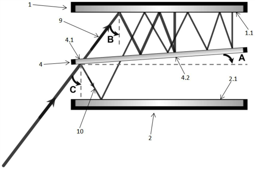
[0072] see figure 1 , a light pulse time stretching device provided by the present invention includes:

[0073] The first reflection mirror 1, the second reflection mirror 2 and the filter 4; the first reflection surface 1.1 of the first reflection mirror 1 and the second reflection surface 2.1 of the second reflection mirror 2 are opposite to each other, The two reflection surfaces 2.1 are parallel; the filter 4 includes a first filter surface 4.1 and a second filter surface 4.2 that are parallel to each other, the first filter surface 4.1 and the first reflection surface 1.1 are spaced apart from each other, and the second filter surface 4.2 and The second reflective surfaces 2.1 are opposite to each other at intervals; the first reflective surface 1.1 and the first filter surface 4.1 form a first included angle A, 0°

[0074] It should be noted that: the light pulses are ultrafast lasers, such as femtosecond lasers, picosecond lasers, etc.; the first reflection surf...

Embodiment 2

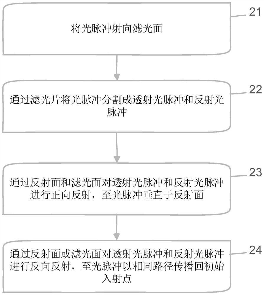
[0088] see Figure 1 to Figure 7 , a light pulse time stretching method provided by the present invention comprises:

[0089] 21. Send the light pulse to the filter surface;

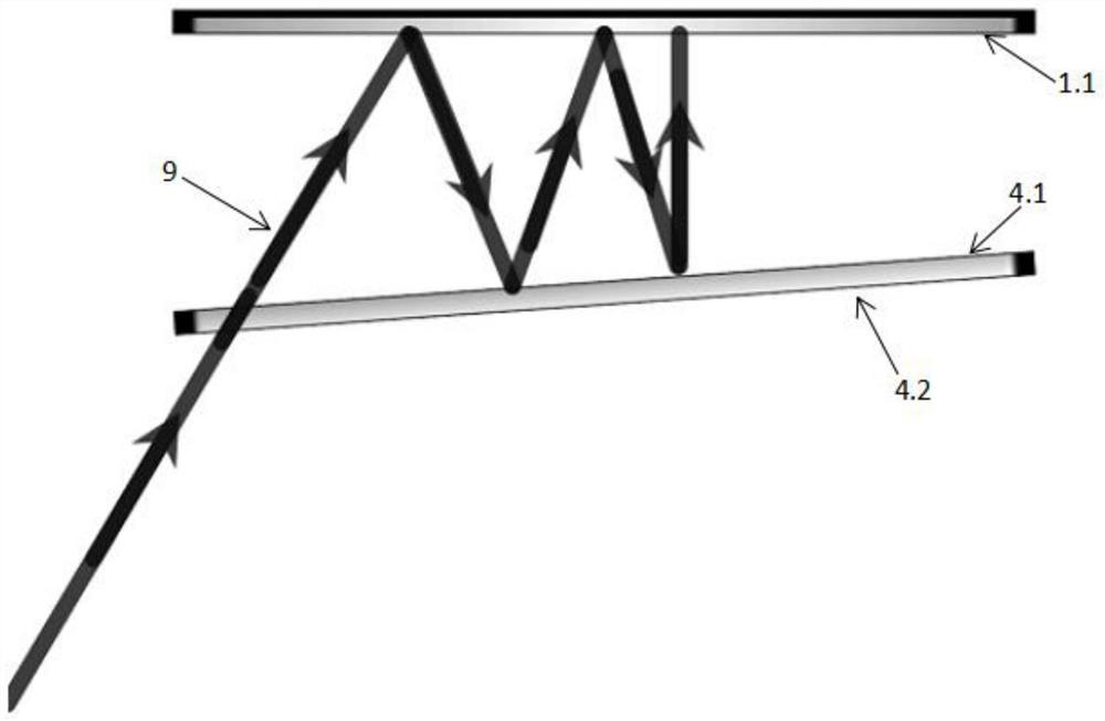
[0090] When the first reflecting mirror 1 and the second reflecting mirror 2 have the same shape and size and are aligned with each other, and the filter 4 is aligned with the first reflecting mirror 1 and the second reflecting mirror 2, the first reflecting mirror 1 and the second reflecting mirror 2 and the filter 4 are centrally symmetric, so the light pulse can be irradiated to one of the first filter surface 4.1 or the second filter surface 4.2, and the same stretching result can be obtained. In this embodiment, the light pulse is reflected to the second filter surface 4.2 as an example for description. In order to reflect the light pulse to the first filter surface 4.1, other devices perform corresponding position adjustment, and the steps to be performed in the method are the same.

[0091] In ...

Embodiment 3

[0112] see figure 1 , Figure 8 and Figure 9 , a spectral measurement system provided by the present invention includes:

[0113] The laser device 5, the commutation device, the optical pulse time stretching device and the signal collection device 8 provided in the first embodiment; the emission end of the laser device 5 corresponds to the incident end of the commutation device; the first outgoing direction of the commutation device points to The second outgoing direction of the filter 4 corresponds to the collecting end of the signal collecting device 8; the straight line of the first outgoing direction and the normal of the filter surface form a second angle C, 0°

[0114] It should be noted that the laser device 8 is used to generate ultrafast laser light, that is, to generate light pulses, and as the light source of light pulses, it can be a picosecond laser, a femtosecond laser or the like.

[0115] The commutation device is used to commutate the ultrafast lase...


PUM

PropertyMeasurementUnit
reflectanceaaaaaaaaaa

Abstract

The invention relates to the technical field of optical measurement, in particular to an optical pulse time stretching device and method and a spectral measurement system, and the device comprises a first reflector, a second reflector and an optical filter; a first reflecting surface of the first reflecting mirror and a second reflecting surface of the second reflecting mirror are opposite at an interval and are parallel to each other; the light filter comprises a first light filtering surface opposite to the first reflecting surface at an interval and a second light filtering surface opposite to the second reflecting surface at an interval, and the first light filtering surface and the second light filtering surface are parallel to each other; the first reflecting surface and the first light filtering surface form a first included angle A which is larger than 0 degree and smaller than 90 degrees. The optical filter is arranged between the reflector pair formed by the first reflector and the second reflector according to a certain included angle, and light pulses with different wavelengths are reflected for different times to realize time stretching. As the reflecting mirror has extremely high reflectivity on the optical pulse of the specific wave band, the generated energy loss is less, and the adjusting device can increase the number of small pulses and the dispersion amount, so that the signal-to-noise ratio of the optical pulse is improved.

Description

technical field [0001] The invention relates to the technical field of optical measurement, in particular to a light pulse time stretching device, method and spectrum measurement system. Background technique [0002] The optical time-stretch imaging method is dedicated to improving the temporal resolution of imaging. This method takes advantage of the decomposability of ultrafast pulsed lasers in the spatial and temporal domains. The spatial information carried by the spectrum realizes information encoding and decoding, and the single-pixel photodetector acts as a receiver to complete continuous ultrafast imaging. Due to the inherent connection between optical time-stretch imaging and optical signal processing, optical time-stretch imaging can be combined with various optical techniques, such as magnification, nonlinear processing, compressed sensing, etc., to achieve unique features that cannot be achieved by traditional image sensors. Function. Many technological achieve...

Claims


Application Information

Patent Timeline
Patent Type & Authority Applications(China)
IPC IPC(8): G02B17/02G02B27/14G01J3/28G01J3/02
CPCG02B17/02G02B27/14G01J3/28G01J3/0208
Inventor 刘伟李中超苏俊昌
Owner SUN YAT SEN UNIV
Why Eureka
Try Eureka