
Efficient power generation system based on liquefied natural gas and working method of efficient power generation system

A technology for liquefied natural gas and power generation systems, which is applied to machines/engines, steam engine installations, mechanical equipment, etc., can solve the problems of compressor stability control, system regulation difficulties, blade water erosion, etc., to reduce the difficulty of sealing technology and improve cycle efficiency. , the effect of reducing heat

Active Publication Date: 2022-07-01
XI AN JIAOTONG UNIV
View PDF6 Cites 0 Cited by
  • Summary
  • Abstract
  • Description
  • Claims
  • Application Information

AI Technical Summary

Problems solved by technology

[0004] Although it has been proven in practice that the impeller machinery of the supercritical carbon dioxide Brayton cycle is more compact than the equipment of the steam Rankine cycle, there are still the following disadvantages: (1) In order to improve cycle efficiency, recompression or triple compression is used. The gas turbine also adopts the double reheating scheme, and the structure is extremely complicated, which brings difficulties to the system regulation; (2) In order to realize multiple compression, multiple reheating and multi-stage recuperation, boilers need to be equipped with multiple Heat transfer in the temperature range to improve boiler efficiency; (3) Due to the compression near the critical point, there is a liquid working medium phenomenon at the compressor inlet, which causes water erosion to the blades and brings difficulties to the stable control of the compressor; (4) The minimum cycle pressure is 7.38MPa, resulting in the enthalpy drop in the gas turbine being about 160kJ / kg, which is far lower than the water vapor cycle. In order to increase the output power of the cycle, the flow rate of the working medium needs to be increased. The pressure loss has a fatal impact

Method used


Image

  • Efficient power generation system based on liquefied natural gas and working method of efficient power generation system

Examples


Embodiment Construction

[0027] The present invention is described in further detail below in conjunction with the accompanying drawings and examples, and its content is to explain rather than limit the present invention:

[0028] Liquid natural gas contains cold energy, which cannot be used well at present; the current cycle efficiency of supercritical carbon dioxide is not high, and the system is complicated. The high-efficiency power generation system based on liquid natural gas of the present invention combines the power cycle of carbon dioxide and the cold energy utilization of liquid natural gas, and solves the current technical problems.

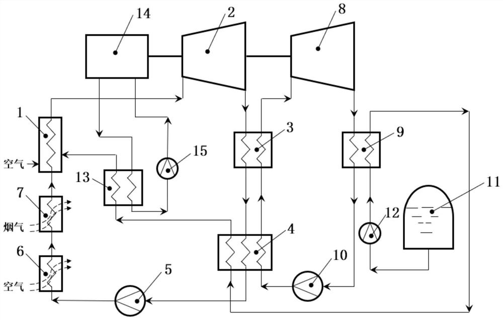
[0029] like figure 1, is the high-efficiency power generation system based on liquid natural gas of the present invention, including a natural gas boiler 1, a carbon dioxide gas turbine 2, a first-stage carbon dioxide heat exchanger 3, a second-stage carbon dioxide heat exchanger 4, a carbon dioxide pump 5, an air heat exchanger 6, a smoke Gas heat exchanger...


PUM


Abstract

The invention discloses an efficient power generation system based on liquefied natural gas and a working method thereof, and belongs to the technical field of power generation systems. The system mainly comprises a natural gas boiler, a carbon dioxide gas turbine, a primary carbon dioxide heat exchanger, a secondary carbon dioxide heat exchanger, an air heat exchanger, a flue gas heat exchanger, an organic working medium gas turbine, an organic working medium heat exchanger, a liquefied natural gas tank, a motor cooling working medium heat exchanger and an ultralow-temperature motor. Liquefied natural gas fuel is used as a cold source, the cooling capacity of liquefied natural gas is utilized in a gradient mode, the working temperature lower limits of carbon dioxide circulation and organic working medium circulation are reduced, and meanwhile the low-temperature organic working medium circulation is coupled to absorb heat released by the carbon dioxide circulation and heat in the atmospheric environment; the working temperature of the motor is reduced, cooling equipment is saved, and energy consumption is reduced; the overall circulation efficiency is improved, the circulation structure is simplified, the investment and operation and maintenance cost of the system are greatly reduced, and the current overall requirements of energy conservation and emission reduction are met.

Description

technical field [0001] The invention belongs to the technical field of power generation systems, and in particular relates to a high-efficiency power generation system based on liquid natural gas and a working method thereof. Background technique [0002] With the promotion of market demand and the continuous development of energy utilization and equipment manufacturing technology, in the past few decades, the large-scale power generation technology of the Rankine cycle using water vapor as the working fluid and the Brayton cycle using gas as the working fluid has always been Towards the direction of high parameters and high power. The analysis found that this development of large-scale power generation technology has improved the energy conversion efficiency and reduced the construction and power generation costs per unit of power. However, the high parameters also make the volume of the generator set very large, and the circulation system is extremely complex, which bring...

Claims


Application Information

Patent Timeline
IPC IPC(8): F01K13/00F01K21/00F01K25/08F01K25/10F01K27/00F01K11/02F01D15/10
CPCF01K11/02F01K25/08F01K25/103F01K27/00F01K13/00F01K21/00F01D15/10
Inventor 邓清华何娟胡乐豪李军丰镇平
Owner XI AN JIAOTONG UNIV
Learn More