
Low-cost and high-efficiency pollutant and CO2 synergistic absorption-desorption decoupling method

A pollutant and low-cost technology, applied in the direction of separation methods, chemical instruments and methods, control/regulation systems, etc., can solve the problems of high cost of solid absorbent, high technical difficulty, waste of sulfur resources, etc., and achieve collaborative capture energy Low consumption, guaranteed absorption efficiency, guaranteed absorption effect

Active Publication Date: 2022-07-08
ZHEJIANG UNIV +1
View PDF10 Cites 0 Cited by
  • Summary
  • Abstract
  • Description
  • Claims
  • Application Information

AI Technical Summary

Problems solved by technology

However, this technology has the following disadvantages: the cost of solid absorbent is high; the regeneration temperature is as high as 150-300°C, and the energy consumption is high; the absorbed SO2 cannot be regenerated, and sulfur resources are excessively wasted
However, this technology has the following disadvantages: the high power consumption of cooling energy recovery leads to much higher energy consumption than traditional chemical absorption methods; the condensation process will produce SO2, CO2 and Impurities other than water vapor, low product purity
[0006] In order to reduce the high cost of separate operation of the existing flue gas purification system and the carbon capture system, develop a new type of absorption system with high absorption rate, large absorption capacity, and low desorption energy consumption Drugs are the most effective method, but due to technical difficulties, a large amount of experimental accumulation is required

Method used


Image

  • Low-cost and high-efficiency pollutant and CO2 synergistic absorption-desorption decoupling method
  • Low-cost and high-efficiency pollutant and CO2 synergistic absorption-desorption decoupling method
  • Low-cost and high-efficiency pollutant and CO2 synergistic absorption-desorption decoupling method

Examples


Embodiment 1

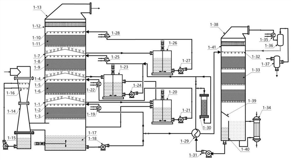
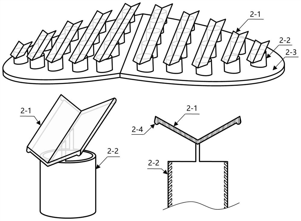
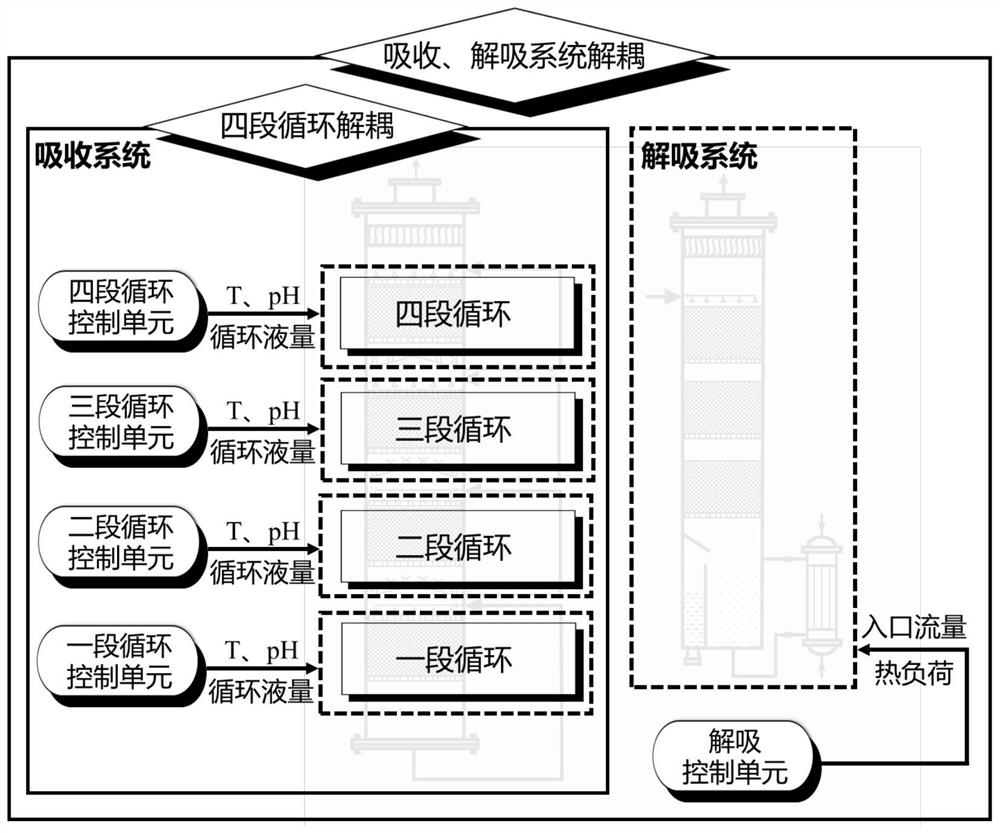
[0078] refer to Figures 1 to 3 , a low-cost and efficient pollutant associated with CO 2 In the coordinated absorption-desorption decoupling method, the flue gas enters the absorption system. The absorption system includes a multi-stage circulating absorption tower. After passing through the pre-washing section set at the front of the multi-stage circulating absorption tower, it enters the first-stage pollutant absorption section and the second-stage CO in turn. 2 Absorption stage, three stage CO 2 The absorption section and the four-stage water washing section; the rich liquid enters the desorption system through the lean and rich liquid heat exchanger, and the desorption system includes a desorption tower. The system and the desorption system are respectively controlled by a decoupling control system. The decoupling control system includes the absorption control unit of the multi-stage circulating absorption tower and the desorption control unit of the desorption tower. Th...

Embodiment 2

[0129] For the flue gas of power plants burning high-sulfur coal containing N 2 and part O 2 In addition, it contains about 10% water vapor, 12% to 18% CO 2 and 1000~1500ppm SO 2 Wait.

[0130]The first-stage circulation control unit is respectively connected with the first-stage circulation tank 1-17, the rich liquid pump 1-18 and the first-stage circulating cooler 1-19, and controls the first-stage circulation independently. The first-stage circulation control unit controls the pH of the absorption liquid in the first-stage circulation tank 1-17, the flow rate of the rich liquid pump circulation 1-18 and the cooling water flow of the first-stage circulating cooler 1-19, so that the first-stage circulation pH is 5.2, and the circulating liquid-gas ratio is 1.8L / m 3 , the absorption temperature is 54 ℃.

[0131] The second-stage circulation control unit is respectively connected with the second-stage circulating pool 1-20, the second-stage circulating pump 1-21 and the se...

Embodiment 3

[0138] For steel mill flue gas containing N 2 and part O 2 In addition, it contains about 5-8% water vapor, 15%-25% CO 2 and 2500~4000ppm SO 2 Wait.

[0139] The first-stage circulation control unit is respectively connected with the first-stage circulation tank 1-17, the rich liquid pump 1-18 and the first-stage circulating cooler 1-19, and controls the first-stage circulation independently. The first-stage circulation control unit controls the pH of the absorption liquid in the first-stage circulation tank 1-17, the flow rate of the rich liquid pump circulation 1-18 and the cooling water flow of the first-stage circulating cooler 1-19, so that the first-stage circulation pH is 4.5, and the circulating liquid-gas ratio is 2.0L / m 3 , the absorption temperature is 58 ℃.

[0140] The second-stage circulation control unit is respectively connected with the second-stage circulating pool 1-20, the second-stage circulating pump 1-21 and the second-stage circulating cooler 1-22,...


PUM


Abstract

The invention relates to a low-cost and high-efficiency pollutant and CO2 synergistic absorption-desorption decoupling method, which establishes a pollutant and CO2 synergistic absorption-desorption decoupling control optimization model under different working conditions, and takes low-cost and high-efficiency obtaining of high-purity liquid pollutants and CO2 as an optimization target. An adaptive penalty function is constructed to convert solution of a constrained optimization problem into an unconstrained optimization problem, and real-time, accurate and stable control of parameters is realized; and by means of flue gas pre-washing cooling, multi-stage intermediate cooling, tower top demisting and the like, efficient trapping of pollutants and CO2 is realized. According to the invention, the absorption process and the desorption process are decoupled, and coordinated regulation and control of each stage of temperature-pH-liquid-gas ratio and rich liquid flow-desorption temperature are carried out, so that efficient and low-energy-consumption coordinated capture-regeneration-concentration of pollutants and CO2 is realized, and the high cost of separated operation of an existing flue gas purification system and a carbon capture system is reduced.

Description

technical field [0001] The invention belongs to the technical field of air pollution control and carbon emission reduction, and specifically relates to a low-cost and high-efficiency pollutant and CO 2 Synergistic absorption-desorption decoupling method. Background technique [0002] Energy is the source of power for economic and social development and civilization progress. Since modern times, the large-scale development and utilization of fossil energy such as coal and oil has effectively improved the production efficiency of various countries, improved the way of life of human beings, and has enabled dozens of countries to realize modernization. However, environmental pollution, energy shortages, climate change and other issues have also become more prominent. The pollutants produced by coal combustion are one of the important causes of air pollution and severe global warming. Coal-fired units and industrial production consume a large amount of coal, and emit large amo...

Claims


Application Information

Patent Timeline
IPC IPC(8): B01D53/14G05B13/04
CPCB01D53/1475B01D53/1406B01D53/1412B01D53/1425G05B13/042B01D2258/0283Y02C20/40B01D15/361B01D53/185B01D53/18B01D47/14B01D47/10B01D2252/103B01D2252/20421B01D2252/20426B01D2252/20431B01D2252/504
Inventor 郑成航高翔刘昶周灿张涌新张悠张杨李钦武翁卫国吴卫红张霄王涛
Owner ZHEJIANG UNIV
Learn More