Oily sludge horizontal stirring, tempering and cleaning device

A cleaning device, mud horizontal technology, applied in sludge treatment, water/sludge/sewage treatment, dehydration/drying/concentrated sludge treatment, etc., can solve the problem of inconvenient oil slick collection and damage to the bearing of the horizontal agitator Dynamic sealing, oil leakage and other problems, to achieve complete mixing and continuous feeding, enhance the effect of stirring, conditioning and cleaning, and ensure the effect of conditioning

Active Publication Date: 2022-07-12
定边县冠博环保科技有限公司
View PDF9 Cites 0 Cited by
  • Summary
  • Abstract
  • Description
  • Claims
  • Application Information

AI Technical Summary

Problems solved by technology

[0004] When the traditional horizontal mixing tank is integrated into skid-mounted equipment, if the stirring shaft is long, it will cause large swing when rotating, which is more likely to cause bearing damage, so the designable reaction volume is usually small; while the vertical mixing tank can realize larger Large volume, but it is very inconvenient to collect slick oil after conditioning and cleaning; horizontal agitation can better realize the sludge conditioning reaction and sludge cleaning function, and at the same time, the scraper can effectively collect the slick oil after conditioning
However, in practical engineering applications, the bearings of the limited horizontal agitator are often damaged, resulting in the problem of oil leakage from the dynamic seal.
Existing oil conditioning and tempering equipment usually requires two mixing tanks / boxes to be alternately fed and tempered during the use process. After the conditioning and tempering reaction is completed, the oil collector is started again, and then the batch type can be used to feed the back-end dehydration equipment, which is automatic to a lesser extent

Method used


Image

  • Oily sludge horizontal stirring, tempering and cleaning device
  • Oily sludge horizontal stirring, tempering and cleaning device
  • Oily sludge horizontal stirring, tempering and cleaning device

Examples


Embodiment Construction

[0023] For a clearer understanding of the purpose, technical solutions and technical effects of the present invention, the present invention is further described below, but the protection scope of the present invention is not limited to the following examples.

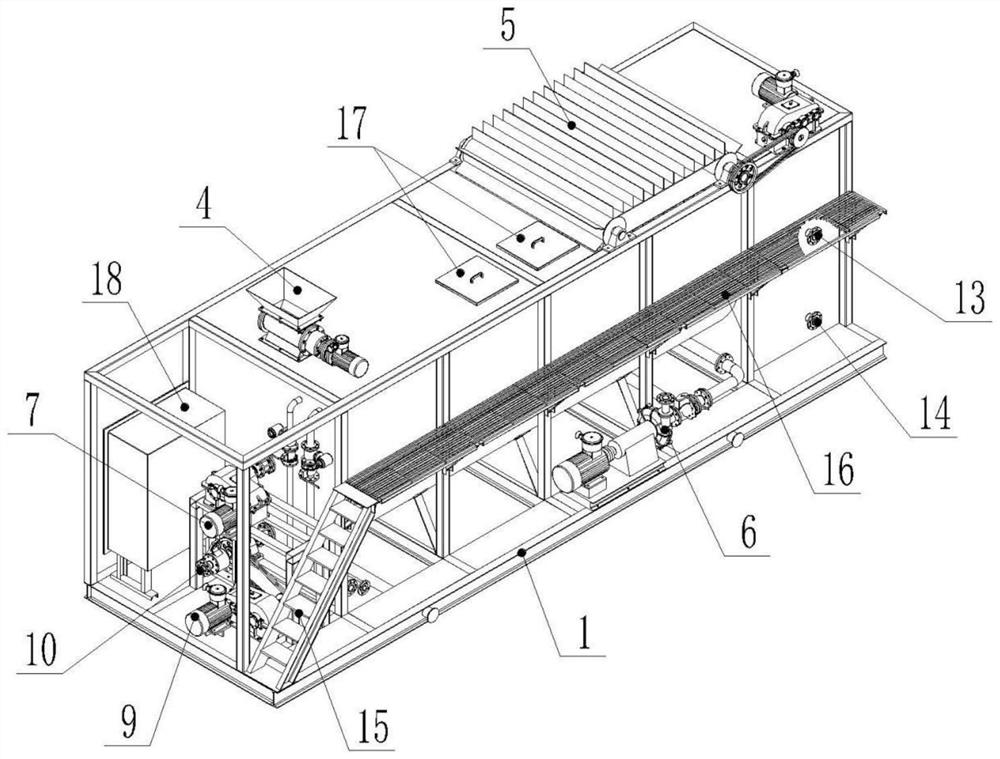
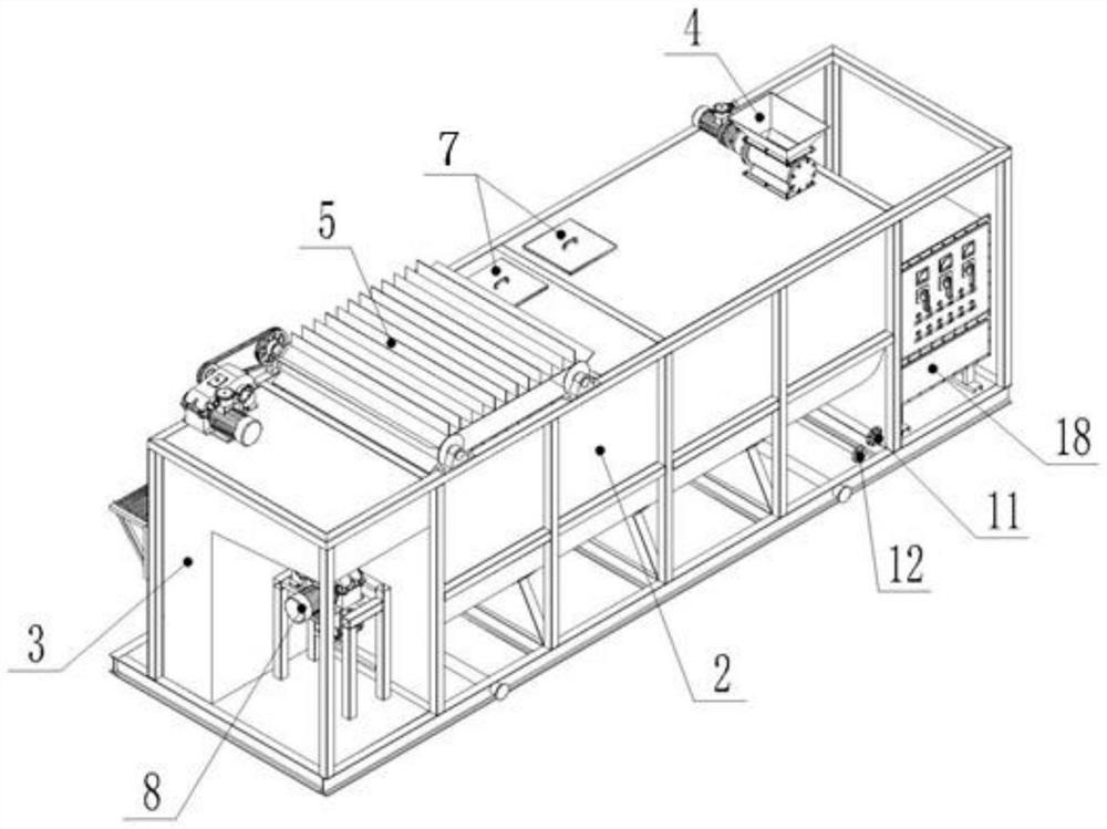
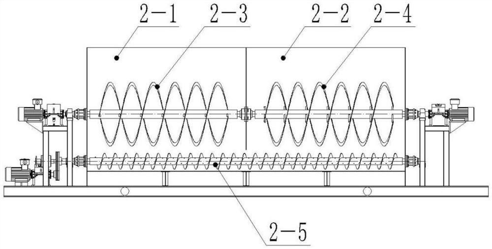
[0024] like Figure 1-3 As shown, a horizontal stirring, conditioning and cleaning device for oily sludge includes: a skid seat (1), a ribbon stirrer (2-3, 2-4), a screw propeller (2-5) and a horizontal stirring tank (2); the horizontal stirring tank (2) includes two different stirring regions, a stirring region A (2-1) and a stirring region B (2-2), and the bottoms of the two different stirring regions are connected; The ribbon stirrer includes a ribbon stirrer a (2-3) and a ribbon stirrer b (2-4), and the ribbon stirrer a (2-3) is arranged in the stirring zone A (2-4). In -1), the ribbon stirrer b (2-4) is arranged in the stirring zone B (2-2); the screw propeller (2-5) is arranged in the horizontal stirring tank ( ...


PUM


Abstract

The invention provides a horizontal stirring, tempering and cleaning device for oily sludge. The horizontal stirring, tempering and cleaning device comprises a helical ribbon stirrer, a spiral propeller and a horizontal stirring tank, the horizontal stirring tank comprises two different stirring areas, namely a stirring area A and a stirring area B; the helical ribbon stirrer a is arranged in the stirring area A, and the helical ribbon stirrer b is arranged in the stirring area B; the spiral propeller is arranged at the bottom of the horizontal stirring tank and penetrates through the bottoms of the two different stirring areas. In the oil sludge hardening and tempering process, a mode of combining a helical ribbon stirrer, helical stirring and airflow stirring is adopted, and the airflow stirring specifically adopts an aeration mode. According to the device, two horizontal helical ribbons are connected in series in a stirring manner, and a bottom helical stirring and flow pushing manner is adopted. The device is high in automation degree and good in tempering and cleaning effects.

Description

technical field [0001] The invention relates to the technical fields of environmental protection, soil remediation, oily sludge treatment and the like, in particular to a horizontal stirring, conditioning and cleaning device for oily sludge. Background technique [0002] The composition of oily sludge is complex, and there are many types of pollutants, such as aged crude oil, suspended solids, clay minerals, flocculation additives, surfactants, corrosion products and heavy metals; it has an extremely stable cream or emulsion system; The compressibility of the mud is about 20 times larger, and the dewatering performance is extremely poor. Among them, the fallen sludge is contaminated with a large number of petroleum pollutants, which not only causes great harm to the environment, but also is a great waste of petroleum resources. The method of chemical cleaning with hot water can be used to recover crude oil. In order to realize the dehydration reduction and resource recovery...

Claims


Application Information

Patent Timeline
Patent Type & Authority Applications(China)
IPC IPC(8): C02F11/14C02F11/12C02F11/00B01F33/82
CPCC02F11/14C02F11/12C02F11/00
Inventor 王旭亮张晓杰黄趾海李强向良知
Owner 定边县冠博环保科技有限公司
Why Eureka
Try Eureka