Wind power generation system pipeline welding machine

A wind power generation system and welding machine technology, applied in wind power generation, welding equipment, welding equipment and other directions, can solve the problems of easy explosion, poor manual welding accuracy, long construction period, etc., so as to improve welding work efficiency and ensure welding quality. , Improve the effect of welding

Active Publication Date: 2022-07-15
常州市沐泽流体科技有限公司
View PDF8 Cites 0 Cited by
  • Summary
  • Abstract
  • Description
  • Claims
  • Application Information

AI Technical Summary

Problems solved by technology

[0003] In the traditional mode, the production of large-scale hydraulic system components is basically completed in the factory, but the hydraulic pipelines are all produced on the user's site. Road disassembly-secondary welding-reassembly, this mode has many disadvantages: the construction period is too long, the quality accuracy is not high, and there is a lot of waste of materials. , the hydraulic equipment is more and more non-standard development, the hydraulic system production is more and more tending to the new mode of factory production and on-site assembly, but the wind turbine is mainly disassembled and transported to the installation site for secondary welding, but the welding accuracy is achieved by manual welding. It is far from meeting the precision requirements of prefabricated pipelines, and it is very easy to burst under the working hydraulic pressure of the wind motor, and the precision is affected by the experience of the welding operator, which leads to the inability to unify the welding standards of the connection points and make it difficult to investigate the responsibility of the accident
[0004] In view of this, the existing problems are studied and improved, and a wind power generation system pipeline welding machine is provided to solve the current problems of inconsistent welding process standards and poor manual welding accuracy. , to achieve the purpose of solving problems and improving practical value

Method used


Image

  • Wind power generation system pipeline welding machine
  • Wind power generation system pipeline welding machine
  • Wind power generation system pipeline welding machine

Examples


Embodiment Construction

[0039] In order to make the objectives, technical solutions and advantages of the present invention clearer, the present invention will be further described in detail below with reference to the specific embodiments and the accompanying drawings. It should be noted that the embodiments of the present invention and the features in the embodiments may be combined with each other under the condition of no conflict.

[0040] It is understood that these descriptions are exemplary only and are not intended to limit the scope of the invention.

[0041] The following describes a wind power generation system pipeline welding machine provided by some embodiments of the present invention with reference to the accompanying drawings.

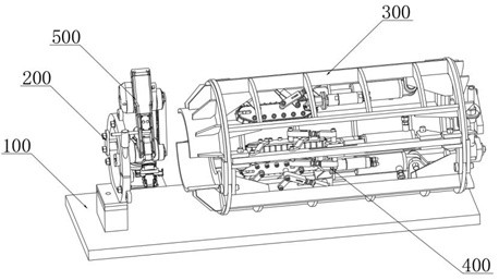
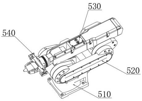
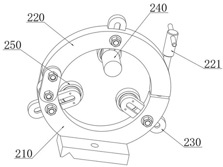
[0042] combine Figure 1-Figure 8 As shown, the wind power generation system pipeline welding machine provided by the present invention includes: a tooling base 100, a fixed tube clamping mechanism 200 fixed on the surface of the tooling base 100, a moving ...


PUM


Abstract

The invention relates to the technical field of wind power generation, in particular to a wind power generation system pipeline welding machine which comprises a tool base, a fixed pipe clamping mechanism fixed to the surface of the tool base, a movable clamping cage, a proofreading feeding mechanism fixedly installed on the inner side of the movable clamping cage and a multi-axis welding mechanical arm. A welding gun head is arranged at the execution tail end of the multi-axis welding mechanical arm, and the circle center axis of the fixed pipe clamping mechanism and the circle center axis of the movable clamping cage are located on the same horizontal line. Automatic welding equipment is arranged, the two ends of a welded pipe are fixed through a movable clamping cage and a proofreading feeding mechanism, and a multi-axis welding mechanical arm is used for conducting servo drive control to achieve pipe body connector welding. Under driving of the calibration feeding mechanism, automatic calibration and feeding joint of the end of the pipe body are carried out, and circumferential deflection of the pipe body is carried out through the pipe fixing clamping mechanism in the welding process, so that automatic and numerical control precise welding of the whole welding process is achieved, the welding quality is guaranteed, and the welding work efficiency is improved.

Description

technical field [0001] The invention relates to the technical field of wind power generation, in particular to a pipeline welding machine of a wind power generation system. Background technique [0002] The wind power source is composed of the wind turbine, the tower supporting the generator, the battery charging controller, the inverter, the unloader, the grid-connected controller, the storage battery, etc. The wind turbine includes the wind wheel, the generator; the wind wheel Including blades, hubs, reinforcements, etc., the pipelines in the hydraulic system of the wind turbine are generally connected by sealing welding. [0003] In the traditional mode, the production of large hydraulic system components is basically completed in the factory, but the hydraulic pipelines are all produced on site. Road disassembly - secondary welding - reassembly, this model has many disadvantages: the construction period is too long, the quality accuracy is not high, and the material was...

Claims


Application Information

Patent Timeline
IPC IPC(8): B23K31/02B23K37/04B23K37/00
CPCB23K31/02B23K37/0435B23K37/00Y02E10/72
Inventor 杨猛谈辉彭网余
Owner 常州市沐泽流体科技有限公司
Why Eureka
Try Eureka