
Controllable rectification circuit and voltage stabilization control method thereof

A rectifier circuit, control signal technology, applied in the direction of control/regulating system, electrical components, regulating electrical variables, etc., can solve the problems of increasing system cost and complexity, long control loop, signal control working status, etc., to eliminate the signal The effect of isolating device requirements and improving response speed

Active Publication Date: 2022-07-22
UNIV OF ELECTRONICS SCI & TECH OF CHINA
View PDF12 Cites 0 Cited by
  • Summary
  • Abstract
  • Description
  • Claims
  • Application Information

AI Technical Summary

Problems solved by technology

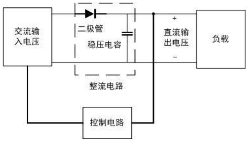
Since the diode is a double-terminal device, the rectifier circuit based on the prior art cannot control its working state through an external control signal, so when performing feedback control based on the prior art, it is usually necessary to convert the feedback signal generated according to the output voltage to the input AC voltage of the rectifier circuit For control, the control loop is long, and an additional signal isolation device is required in the isolated switching power supply to transmit the signal from the secondary side back to the primary side, which increases the system cost and complexity

Method used


Image

  • Controllable rectification circuit and voltage stabilization control method thereof
  • Controllable rectification circuit and voltage stabilization control method thereof
  • Controllable rectification circuit and voltage stabilization control method thereof

Examples


Embodiment Construction

[0030] In order to make the above-mentioned objects, features and advantages to be achieved by the present invention more obvious and easy to understand, preferred embodiments are given below and described in detail in conjunction with the accompanying drawings.

[0031] like Image 6 As shown, it is a circuit structure diagram of an isolated voltage converter with voltage regulation based on the controllable rectifier circuit of the present invention, including a full-bridge inverter circuit, a transformer, a rectifier circuit and a load.

[0032] The rectifier circuit adopts the controllable rectifier circuit described in the present invention. The AC input voltage of the controllable rectifier circuit is provided by the secondary winding of the transformer. Optionally, the rectifier circuit includes Figure 4 The described two-phase controllable rectifier circuit, and as Figure 5 The described control signal generating circuit. The control signals generated by the cont...


PUM


Abstract

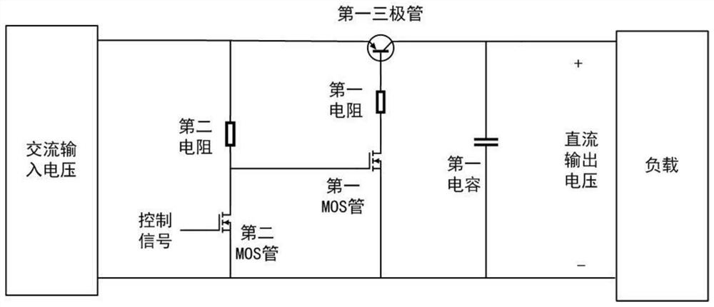
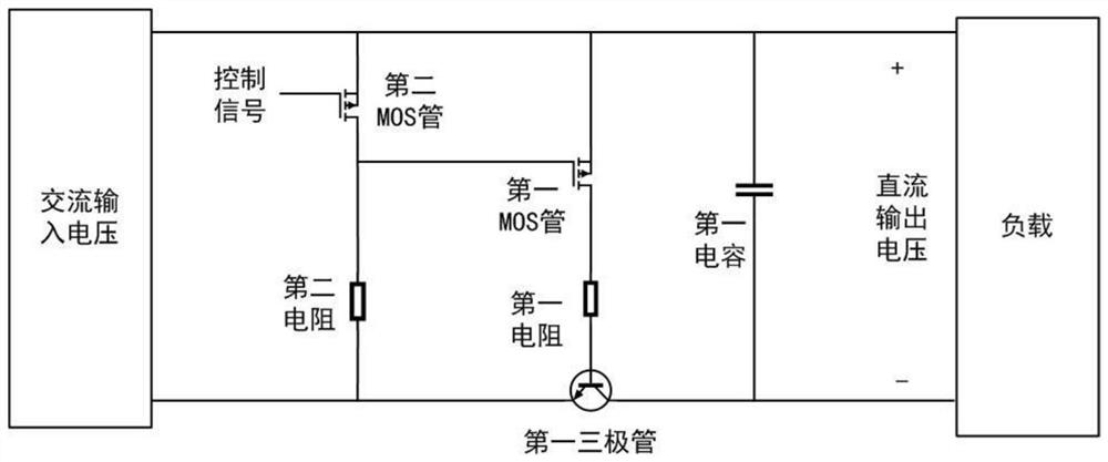
A controllable rectifying circuit is characterized by comprising a first triode, a first MOS (metal oxide semiconductor) tube, a second MOS tube, a first resistor, a second resistor, a first capacitor, an emitting electrode of the first triode and a first end of the second resistor are coupled with a first end of input voltage of the controllable rectifying circuit, and a second end of the second resistor is coupled with a second end of input voltage of the controllable rectifying circuit. The collector electrode of the first triode and the first end of the first capacitor are coupled with the first end of the controllable rectifying circuit for outputting voltage, the base electrode of the first triode is coupled with the first end of the first resistor, and the drain electrode of the first MOS tube is coupled with the second end of the first resistor; the grid electrode of the first MOS transistor is coupled with the drain electrode of the second MOS transistor and the second end of the second resistor, the source electrode of the first MOS transistor, the source electrode of the second MOS transistor and the second end of the first capacitor are coupled with the second end of the controllable rectification circuit input voltage, and the grid electrode of the second MOS transistor is used for accessing a control signal.

Description

technical field [0001] The invention relates to the fields of power electronics and integrated circuits, in particular to a controllable rectifier circuit and a voltage regulation control method thereof. [0002] technical background [0003] In daily use, electronic systems often need to draw energy from the AC power source and convert it into a stable DC power source that can be used by other components. Therefore, the modern power supply design work usually involves the AC-DC conversion part. The rectifier circuit is a circuit that can convert the input AC power into DC voltage output. It is widely used and is often used in circuit design such as isolated power supplies. [0004] When the rectifier circuit is used in applications such as wireless power transmission and isolated power supply, the AC power will be transmitted from the primary winding to the secondary winding through magnetic coupling. The rectifier circuit is usually placed after the secondary winding to con...

Claims


Application Information

Patent Timeline
Patent Type & Authority Applications(China)
IPC IPC(8): H02M7/219H02M3/335
CPCH02M7/219H02M3/33576Y02B70/10
Inventor 伍荣翔周子敬
Owner UNIV OF ELECTRONICS SCI & TECH OF CHINA
Learn More