
Method for recovering high-purity tin-indium alloy from ITO target waste

A waste recycling and high-purity tin technology, which is applied in instruments, electrolytic components, optics, etc., can solve the problems of long electrolysis time and achieve the effect of improving the recovery rate and avoiding the short circuit of cathode and anode

Pending Publication Date: 2022-07-29
柳州华锡有色设计研究院有限责任公司
View PDF17 Cites 0 Cited by
  • Summary
  • Abstract
  • Description
  • Claims
  • Application Information

AI Technical Summary

Problems solved by technology

This method takes a long time for electrolysis, and the highest recovery rate of indium tin alloy is only 75%

Method used


Image

  • Method for recovering high-purity tin-indium alloy from ITO target waste
  • Method for recovering high-purity tin-indium alloy from ITO target waste

Examples


Embodiment 1

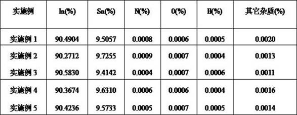
[0026] Example 1, Example 2 and Example 3 adopt the dimensions of the anode plate and the cathode plate: the length, width and thickness of the anode plate are 19.80cm, 13.80cm, and 0.90cm in sequence; the length, width and thickness of the cathode plate are 12.38cm, 8.63cm cm, 0.20 cm.

Embodiment 4

[0027] The dimensions of the anode plate and cathode plate used in Examples 4 and 5 are: the length, width and thickness of the anode plate are 20.20cm, 14.20cm, and 1.10cm in turn; the length, width and thickness of the cathode plate are 14.42cm, 10.15cm, and 0.30cm in turn .

[0028] Example 1:

[0029] (1) Dissolution: The anode plate and the titanium cathode plate are placed in the first electrolytic cell, and 800g / l sulfuric acid is used as the electrolyte for the first microcurrent electrolysis. The current density of the first microcurrent electrolysis is 40A / m. 2 , the temperature is 20°C, the electrolysis time is 120min, and the indium tin solution in the first electrolytic cell is taken;

[0030] (2) Primary purification: The anode plate and the titanium cathode plate are placed in the second electrolytic cell, and the indium tin solution is used as the electrolyte for the second micro-current electrolysis. The current density of the second micro-current electrolysi...

Embodiment 2

[0033] (1) Dissolution: The anode plate and the titanium cathode plate are placed in the first electrolytic cell, and 800g / l sulfuric acid is used as the electrolyte to carry out the first microcurrent electrolysis. The current density of the first microcurrent electrolysis is 45A / m. 2 , the temperature is 40°C, the electrolysis time is 160min, and the indium tin solution in the first electrolytic cell is taken;

[0034] (2) Primary purification: The anode plate and the titanium cathode plate are placed in the second electrolytic cell, and the indium tin solution is used as the electrolyte for the second micro-current electrolysis. The current density of the second micro-current electrolysis 60A / m 2 , the temperature is 40℃, and the electrolysis time is 130min;

[0035] (3) Secondary purification: filter out the moisture from the indium-tin alloy precipitate at the bottom of the second electrolytic cell and place it in a graphite crucible, then put it into a high-purity Ar su...


PUM

PropertyMeasurementUnit
concentrationaaaaaaaaaa

Abstract

The invention relates to a method for recovering high-purity tin-indium alloy from ITO (indium tin oxide) target waste, which takes the ITO target waste as an anode plate, and comprises the following steps: (1) dissolving; (2) primary purification; and (3) secondary purification. The large-size anode plate and the small-size cathode plate form a weak non-uniform electric field under the action of micro current, indium and tin in the ITO target material waste are rapidly dissolved in the electrolyte to form a pure indium and tin solution under the non-uniform electric field, then the indium and tin solution is used as the electrolyte to perform secondary micro-current electrolysis, and due to the fact that the electric field is non-uniform, the indium and tin in the ITO target material waste are subjected to secondary micro-current electrolysis. The indium-tin alloy does not drift to the cathode for deposition but rapidly sinks to the bottom of the electrolytic bath, so that cathode and anode short circuit is avoided; according to the method, the recovery rate of the indium-tin alloy is increased to 80% or above.

Description

technical field [0001] The invention belongs to the field of ITO powder production, and particularly relates to a method for recovering high-purity tin-indium alloy from ITO target waste. Background technique [0002] With the rapid development of electronic information technology, liquid crystal displays are widely used, and the consumption of ITO targets, which are the raw materials for the production of indium tin oxide thin films, is also increasing significantly. The utilization rate of ITO targets in the production of ITO films is low, and about 70% of the ITO targets become waste and need to be recycled. The composition of the ITO target is generally indium oxide and tin oxide with a mass ratio of 9:1. The content of metal indium in the waste target is about 74.40%, and the content of metal tin is about 7.88%. Both indium and tin metals are precious metals. The content of indium in the earth's crust is 1×10⁻⁵%, and it is relatively dispersed. So far, no rich ore has ...

Claims


Application Information

Patent Timeline
Patent Type & Authority Applications(China)
IPC IPC(8): C25C1/22C25C1/14C25C7/06C25C7/02
CPCC25C1/22C25C1/14C25C7/06C25C7/02Y02P10/20
Inventor 农永萍胡明振徐灿辉王莉莉赵明勇樊繁林成旭覃祚明
Owner 柳州华锡有色设计研究院有限责任公司
Learn More