
Outboard device of submarine radar

An external device and radar technology, which is applied in the direction of antenna support/installation device, base/casing, radiation unit cover, etc., can solve the problems of high erection requirements, poor anti-interception performance, low reliability, etc., and achieve speed and rotation angle control Simplicity, enhanced anti-interception performance, and improved work reliability

Pending Publication Date: 2022-07-29
SHAANXI CHANGLING ELECTRONICS TECH
View PDF0 Cites 0 Cited by
  • Summary
  • Abstract
  • Description
  • Claims
  • Application Information

AI Technical Summary

Problems solved by technology

The azimuth error caused by the torsion effect of the first type of radar mast is relatively large, so the existing submarine radar usually uses the second type of outboard device to install a driving device to drive the radar antenna to rotate itself, thereby improving the accuracy of the radar azimuth, but this rotation method at the same time It also brings new problems: one is that the outboard device needs to withstand seawater pressure and keep it sealed, and the dynamic sealing problem caused by its drive unit; the other is how to transmit the electromagnetic wave signal of the antenna, which has always been a technical problem for submarine radar.
[0007] 1) It is necessary to use the inner cavity of the mast to seal the feeders and cables that do not have the sealing ability at the bottom of the outboard device. There are many sealing points, high erection requirements, and low reliability.
[0008] 2) The hydraulic motor directly drives the main shaft to drive the antenna to rotate. Since the radar antenna needs to work at multiple speeds in forward and reverse directions, there are problems such as complex structure of oil circuit and control system, high mechanical noise and low reliability.
[0009] 3) The microwave signal of the antenna is transmitted through the waveguide. Because the waveguide is a rigid hard connection, and the submarine radar antenna has lifting movements during use and recovery, the docking of the waveguide must use a catcher. The structure of the radar antenna feeder system is complex and the failure rate is high.
[0010] 4) The dynamic seal of the main shaft is a pressure-bearing seal, and there is seawater leakage. The leakage channel must be preset inboard, and the leaked seawater will affect the transmission performance of the radar waveguide system and the transmission of the radar antenna azimuth signal, which may easily cause radar feedback. wave failure
[0011] 5) The recovery of the parabolic antenna takes up a lot of space, which is not conducive to the miniaturization of the submarine bridge
[0012] 6) Poor anti-interception performance
[0013] The anti-interception performance of submarine radar is very important to the concealment of submarines. However, since the single-antenna non-continuous wave radar currently used cannot obtain good anti-interception performance, to obtain good anti-interception performance, it is necessary to use dual-antenna continuous wave radar. In practice, due to the small installation space of the submarine radar antenna, its antenna size, especially the height, is strictly limited, and it is impossible to arrange dual parabolic antennas. If an array antenna is used instead, there will be seawater pressure-resistant sealing problems and a thick radome. The large loss caused by the problem affects the performance of the antenna

Method used


Image

  • Outboard device of submarine radar
  • Outboard device of submarine radar
  • Outboard device of submarine radar

Examples


Embodiment Construction

[0043] The embodiments of the present invention will be described in detail below with reference to the accompanying drawings.

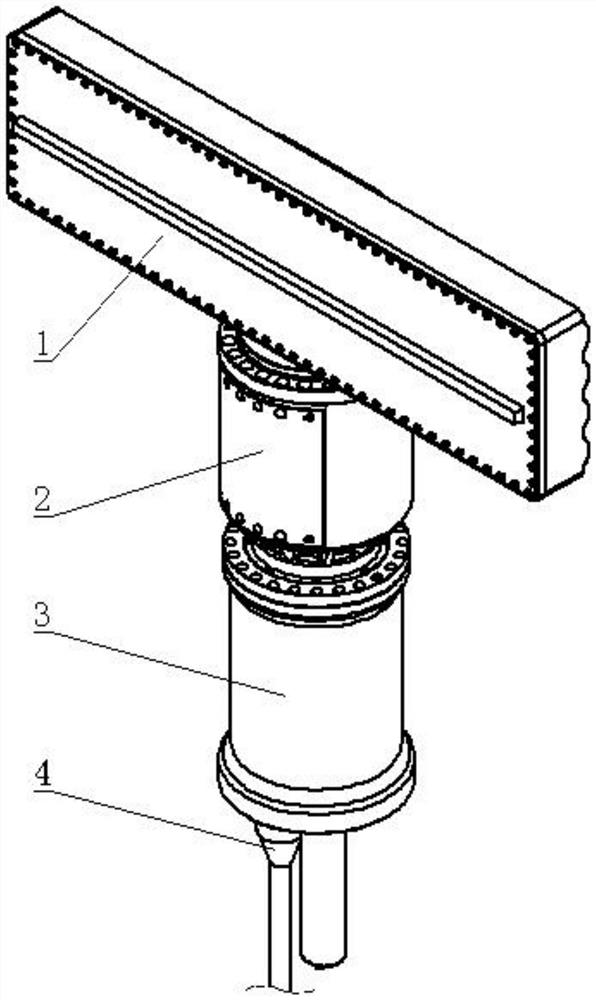
[0044] refer to figure 1 , the outboard device of this embodiment is in the shape of a "T" as a whole, and consists of an antenna unit 1, a transceiver unit 2, a drive unit 3 and a watertight cable assembly 4 connected in sequence from top to bottom, and these four units are all water pressure resistant. Seal the housing, and O-rings are also used between the units to form a water pressure-resistant seal as a whole.

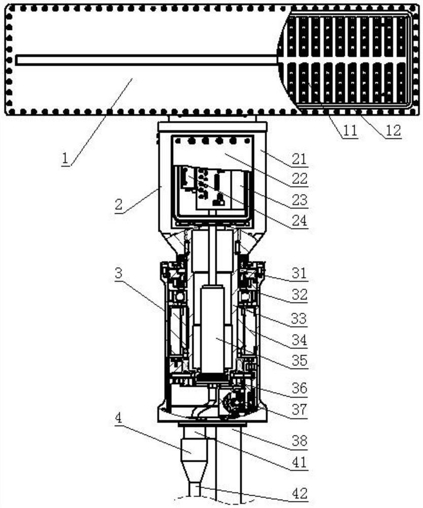
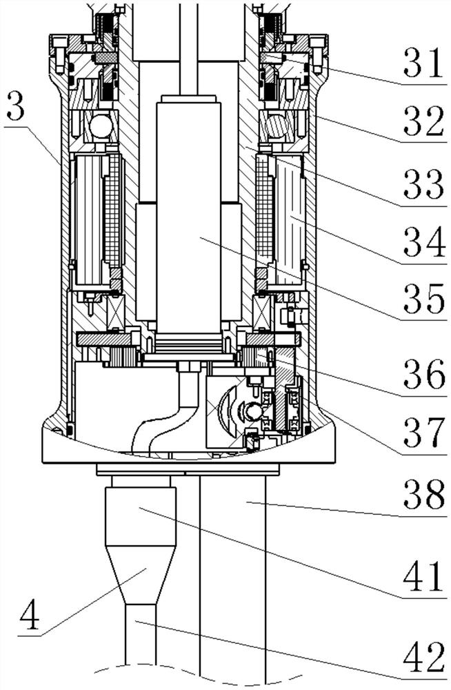
[0045] refer to figure 2 , the antenna unit 1 adopts a flat slit array antenna with a thickness of 100mm in the shape of a cuboid, which includes an antenna 11 and a radome 12, the antenna includes a transmitting antenna array and a receiving antenna array, forming two functionally independent microwave signal channels, transmitting An isolation structure is provided between the antenna array and the receiving antenna array to meet t...


PUM


Abstract

The invention discloses an outboard device of a submarine radar. The outboard device mainly solves the problems that an existing outboard device of the submarine radar is prone to seawater leakage, large in working noise, complex in signal transmission system, high in erection requirement and failure rate and poor in interception resistance. An antenna unit (1), a transmitting-receiving unit (2), a driving unit (3) and a watertight cable assembly (4) which are all provided with water-pressure-resistant sealing shells are sequentially connected in a sealed mode to form a water-pressure-resistant sealing body. The antenna unit can simultaneously transmit and receive radar electromagnetic waves; the transceiving unit is used for generating a microwave signal, transmitting the microwave signal to the antenna unit and performing down-conversion processing on the received microwave signal; the driving unit is electrically driven, is filled with an insulating medium and is additionally provided with a pressure balance compensation device; the watertight cable assembly is used for being electrically connected with inboard equipment. The system has the advantages of capability of avoiding seawater leakage, low working noise and erection requirements, simple system structure, low failure rate and better anti-interception performance, and can be used for continuous wave transceiver system radar equipment.

Description

technical field [0001] The invention belongs to the technical field of submarine radar, in particular to an outboard device, which can be used for submarine radar equipment of a continuous wave transceiver system. Background technique [0002] Submarine radar is a special electronic device mainly used for sea search and navigation. [0003] Submarine radar is mainly composed of radar antenna, transmitter, receiver, data processing equipment and terminal equipment. Depending on the installation location, it can be divided into two parts: outboard device and inboard device. Among them: [0004] Traditional inboard equipment includes transmitter, receiver, data processing equipment and terminal equipment, and there are no special requirements for the use environment of these equipment. [0005] The traditional outboard device is a radar antenna. Since the radar antenna must extend out of the hull to receive and transmit electromagnetic waves, the radar antenna must be installe...

Claims


Application Information

Patent Timeline
Patent Type & Authority Applications(China)
IPC IPC(8): H01Q1/34H01Q1/22H01Q1/24H01Q1/36H01Q1/42H01Q1/50H01R13/52H04B1/40
CPCH01Q1/34H01Q1/50H01Q1/22H01Q1/42H01Q1/24H01R13/5205H01Q1/36H04B1/40
Inventor 汪世勇王文军张亚乔柳志鑫荆恒唐北奇梁猛彭良王圣超
Owner SHAANXI CHANGLING ELECTRONICS TECH
Learn More