Single-chip microcomputer control circuit with built-in high-voltage-resistant charging management and motor driving circuit
A technology of motor drive circuit and charging management circuit, applied in computer control, program control, general control system, etc., can solve the problems of difficulty affecting PCB layout and production and processing, inability to support wireless charging, and high cost
- Summary
- Abstract
- Description
- Claims
- Application Information
AI Technical Summary
Problems solved by technology
Method used
Image
Examples
Embodiment 1
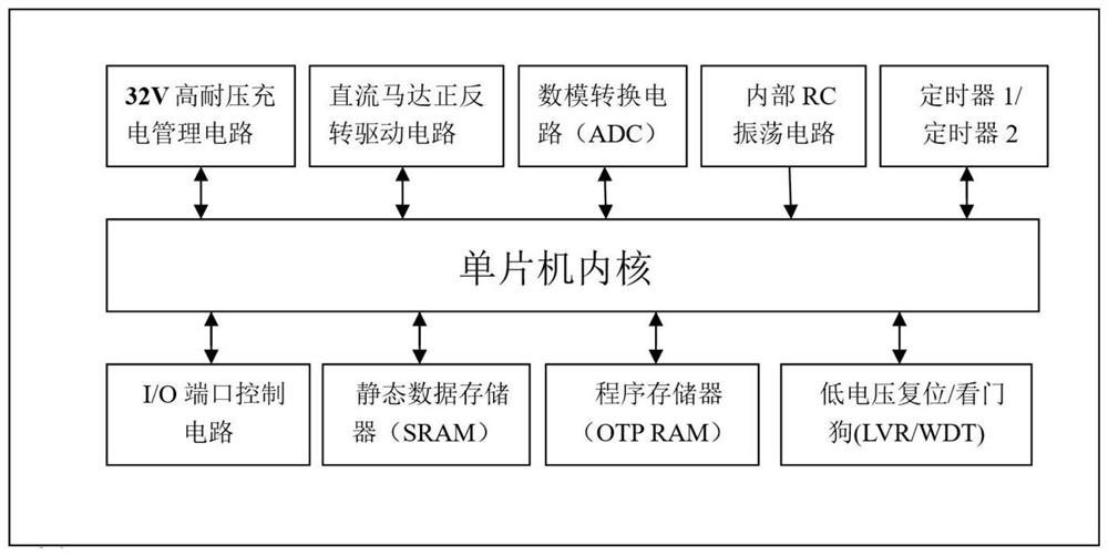
[0033] Please refer to figure 1 ,Built-in high-voltage charging management and single-chip motor drive circuit control circuit, the main control chip uses a 4-bit reduced instruction set single-chip microcomputer core as the core, and integrates 32V high-voltage charging management circuit, DC motor forward and reverse drive circuit, Internal integrated one-time programmable program memory (OTP ROM), digital-to-analog conversion circuit (ADC), static data memory (SRAM), low-voltage reset circuit (LVR), watchdog circuit (WDT), timer 1 and timer 2 , Internal oscillator circuit (IRC), port control circuit (GPIO). By writing the microcontroller software and burning the final binary code into the program memory through the programmer, it can realize the lithium battery-powered electric toothbrush, electric shaver and other small household appliances solutions with different functions. This scheme has the characteristics of high integration, less peripherals, low power consumption,...
Embodiment 2
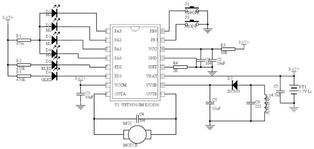
[0034] Embodiment 2, this design also discloses an electric toothbrush, including the single-chip control circuit in Embodiment 1, such as figure 2 As shown, the microcontroller control circuit is chip U1, which also includes motor MG1, capacitor C4, switch S1 and switch S2. Pin 1 of chip U1 is connected to the cathode of LED D1, and pin 2 of chip U1 is connected to the cathode of LED D2. Chip U1 The pin 3 of the chip U1 is connected to the cathode of the LED D3, the pin 4 of the chip U1 is connected to the cathode of the LED D4, the pin 5 of the chip U1 is connected to the cathode of the LED D5, the pin 6 of the chip U1 is connected to the cathode of the LED D6, the The anode is connected to the anode of the LED D2, the anode of the LED D3, the anode of the LED D4 and the resistor R1, the anode of the LED D5 is connected to the resistor R2, the anode of the LED D6 is connected to the resistor R3, and the other end of the resistor R1 is connected to the resistor R2. The other...
Embodiment 3
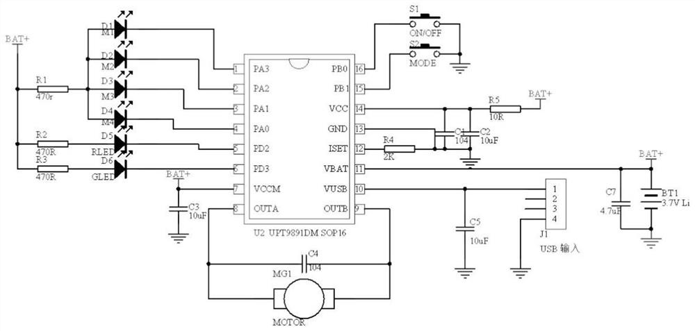
[0036] Example 3, as image 3 As shown, the difference from Embodiment 2 is that the pin 10 of the chip U1 is connected to the USB interface J1 and the capacitor C5, the other end of the capacitor C5 is grounded, and the USB interface 5V power supply is used instead of the wireless charging power supply.
PUM
 Abstract
Description
Claims
Application Information
 - R&D
- Intellectual Property
- Life Sciences
- Materials
- Tech Scout
- Unparalleled Data Quality
- Higher Quality Content
- 60% Fewer Hallucinations
Browse by: Latest US Patents, China's latest patents, Technical Efficacy Thesaurus, Application Domain, Technology Topic, Popular Technical Reports.
© 2025 PatSnap. All rights reserved.Legal|Privacy policy|Modern Slavery Act Transparency Statement|Sitemap|About US| Contact US: help@patsnap.com


