
Method for flue gas desulfurization and flue gas desulfurization system

A flue gas and system technology, applied in the field of flue gas desulfurization, can solve the problems of increased operating costs, no coexisting components, complexity, etc., and achieve the effects of increasing the size of equipment, avoiding the size of equipment, and simplifying the treatment process

Inactive Publication Date: 2001-07-18
MITSUBISHI HEAVY IND LTD
View PDF0 Cites 19 Cited by
  • Summary
  • Abstract
  • Description
  • Claims
  • Application Information

AI Technical Summary

Problems solved by technology

[0004] However, when this method is used, magnesium in the desulfurization wastewater is precipitated as magnesium hydroxide, so that a large amount of sludge is generated, thereby posing a problem that the size of the sludge treatment facility increases
In addition, because this treated water has a high pH, ​​further downstream treatment of other pollutants (such as fluorine) is necessary, or the pH must be lowered to a value close to neutral in order to meet discharge regulations. There is such a problem: the increase in operating costs
Therefore, there is such a disadvantage: it takes a lot of chemicals and a lot of manpower
[0012] Although N-S compounds in desulfurization wastewater can be treated by this treatment method, there is still no suitable method to comprehensively treat coexisting components (such as manganese and other heavy metals) and organic COD components.
Moreover, the organic COD components contained in desulfurization wastewater are also difficult to decompose
Therefore, there arises a problem that in order to sufficiently absorb and remove organic components, it is necessary to increase the size of the adsorption equipment
[0017] Such a conventional treatment method has a problem that the desulfurization wastewater treatment process for flue gas desulfurization is large-scale and complicated, and also generates a large amount of waste
[0024] Therefore, whether the effective combination of the desulfurization process and the wastewater treatment process can be used as a whole system to promote this treatment, simplify the treatment equipment and reduce the amount of sludge has not been fully studied.

Method used


Image

  • Method for flue gas desulfurization and flue gas desulfurization system
  • Method for flue gas desulfurization and flue gas desulfurization system
  • Method for flue gas desulfurization and flue gas desulfurization system

Examples


Embodiment 1

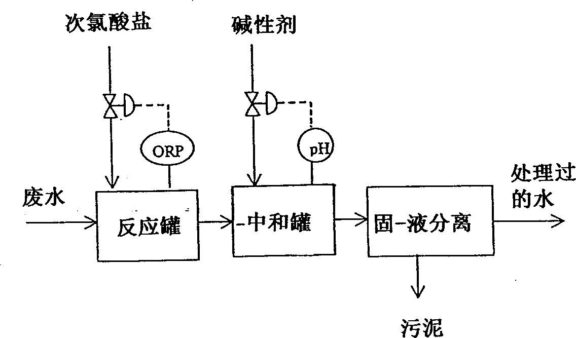
[0244] As the wastewater discharged from the desulfurizer of boiler combustion flue gas, under the treatment conditions given in Table 2, use figure 1 The scheme shown treats desulfurization wastewater having the water qualities given in Table 1 below. Table 2 gives the treated water quality and the amount of sludge generated in this treatment.

[0245] It can be seen from Table 2 that if the amount of chlorine added is 50 mg / L or greater, then manganese ions Mn in the treated water 2+ The amount is 10 mg / L or less.

[0246] pH value

[0247] Reactor Chlorine added (mg / L) 20 50 100 ORP(mV) 450 600 780 Neutralization tank pH(-) 8 8 8 ORP(mV) 430 580 750 Residual Chlorine (mg / L) >0.05 12 17 treated water mn 2+ (mg / L) 30 8 >1 Amount of sludge (mg / L): SS 10 45 60

Embodiment 2

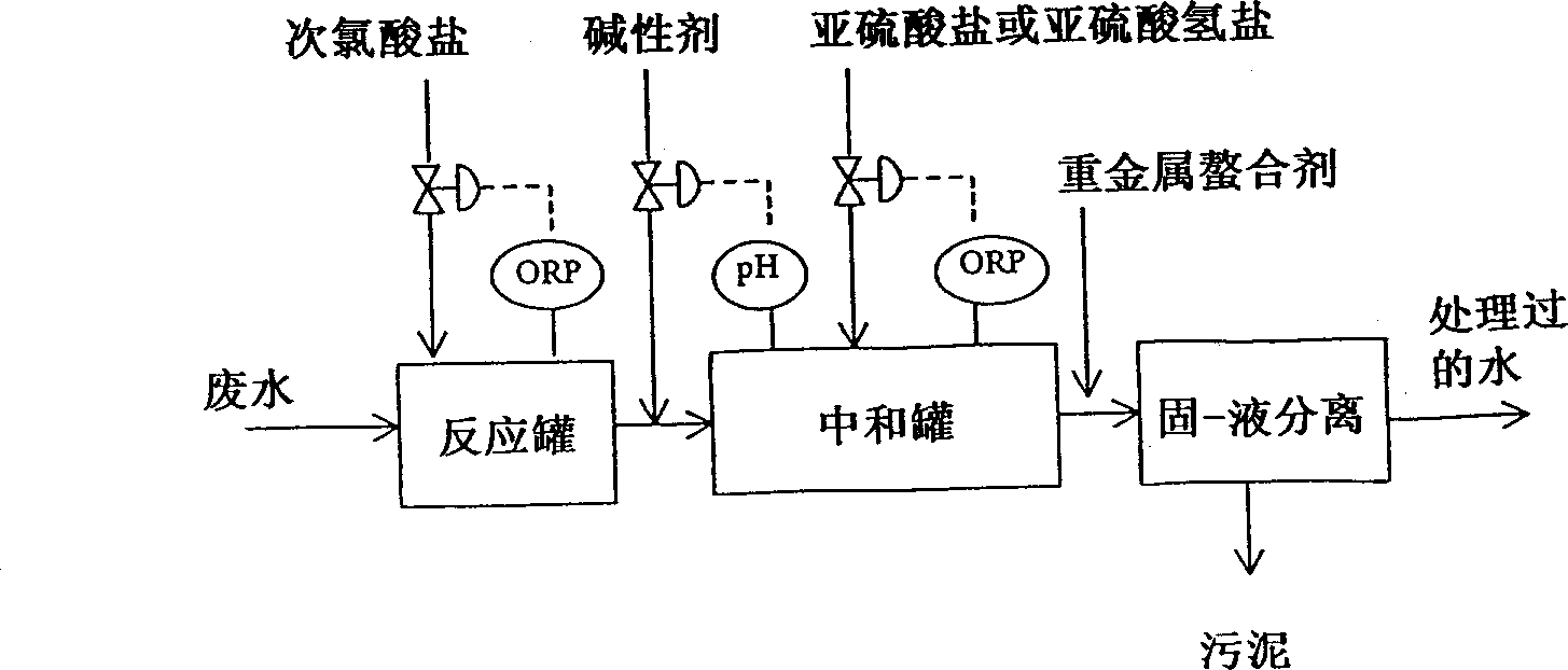
[0251] As in the case of Working Example 1, under the treatment conditions given in Table 3 with figure 2 The process shown treats desulfurization wastewater with the water quality given in Table 1. The treated water quality and the amount of sludge generated in this treatment are listed in Table 3.

[0252] As can be seen from Table 3, the amount of manganese ions in the treated water is 1 mg / L or less, but if there is residual chlorine in the neutralization tank, cadmium cannot be removed at all; Or sulfite ion excess treatment conditions, cadmium is removed.

[0253] Reactor Chlorine added (mg / L) 100 100 100 ORP(mV) 780 780 780 Neutralization tank PH(-) 8 8 8 Added bisulfite (mg / L) 0 50 100 ORP(mV) 750 350 200 Residual Chlorine (mg / L) 17 <0.05 <0.05 residual So 3 2- (mg / L) - <1 <1 Added heavy metal chelating agent (mg / L) 30 30 30 treated water mn 2+ (mg / L) <1 <1 <1 Cd 2+ (mg / L) 0...

Embodiment 3

[0255] As in the case of Working Example 1, under the treatment conditions given in Table 4, with figure 2 The flow shown treats desulfurization wastewater with the water qualities given in Table 1. The treated water quality and the amount of sludge generated in this treatment are listed in Table 4.

[0256] Reactor Chlorine added (mg / L) 100 100 100 ORP(mV) 750 750 750 PH(-) 9 9 9 Neutralization tank Added bisulfite (mg / L) 0 50 100 ORP(mV) 750 350 170 Residual Chlorine (mg / L) 17 <0.05 <0.05 residual So 3 2 (mg / L) - <1 7 Added heavy metal chelating agent (mg / L) 30 30 30 treated water mn 2+ (mg / L) <1 <1 1.6 Cd 2+ (mg / L) 0.5 <0.1 <0.1 Amount of sludge (mg / L) 70 70 70

[0257] As can be seen from Table 4, when residual chlorine was present in the neutralization tank (OPR 750 mV), the amount of manganese ions in the treated water was 1 mg / liter or less, but cadmium could not...


PUM


Abstract

The invention provides a method for treating a drain water from a wet flue gas desulfurization apparatus for removing sulfur oxides in a flue gas by the wet lime-gypsum method, characterized as comprising adding a hypochlorite to the drain water, and then adjusting the pH of the resulting mixture to a value of 7 to 9.5, followed by separation between a solid and a liquid; and a method for desulfurizing a flue gas containing sulfur oxides and nitrogen oxides by the wet lime method, characterized as comprising an oxidizing step comprising drawing out a part of the slurry formed by absorption in a desulfurization step, followed by separation of gypsum, adjusting the pH of the resultant filtrate to a value of 3 to 4, and adding an oxidizing agent, a neutralizing step comprising adjusting the pH of the mixture resulting from the oxidizing step to a value of 7 to 9.5, and a solid-liquid separation step comprising separation between a solid and a liquid of the neutralized mixture. Accroding to the invention, these methods can be employed for removing NS compounds effectively, which affect adversely the desulfurization performance of the apparatus, and at the same time for removing heavy metals in the desulfurization drain water, particularly manganese, with economical advantage.

Description

technical field [0001] The invention relates to a flue gas desulfurization method, which includes the treatment of desulfurization waste water, the treatment of absorbent slurry and the flue gas desulfurization system. More particularly, the present invention relates to a method for flue gas desulfurization by the wet lime-gypsum process, in which the sulfur oxides and nitrogen oxides in the flue gas are treated with an absorbent slurry of limestone or slaked lime Absorption and separation; relates to a flue gas desulfurization system enabling the above-mentioned process to be properly carried out, and to a treatment method for the above-mentioned absorbent slurry, a method for effectively treating the waste water generated when combustion fumes The sulfur oxides in the flue gas are desulfurized by the wet lime-gypsum method, especially by soot mixed desulfurization treatment, pollution-free treatment, etc., and the waste water is discharged. technical background [0002] C...

Claims


Application Information

Patent Timeline
IPC IPC(8): B01D53/14B01D53/50B01D53/73C02F1/28C02F1/42C02F1/44C02F1/52C02F1/56C02F1/64C02F1/66C02F1/68C02F1/70C02F1/72C02F1/74C02F1/76C02F9/00C02F9/04
CPCC02F1/72B01D53/50C02F1/283C02F1/5236C02F1/725C02F1/444C02F1/66B01D53/1425C02F2101/10B01D53/501C02F9/00C02F1/683C02F2103/18C02F1/74C02F1/44C02F1/766B01D53/73C02F2303/185C02F1/56C02F1/76C02F1/70C02F1/42C02F1/64C02F1/52C02F2209/04C02F2209/06C02F2101/20
Inventor 吉冈笃岩下浩一郎越智英次篠田岳男冲野进神吉秀起马场博伊藤哲也远藤笃昌西田守贤
Owner MITSUBISHI HEAVY IND LTD
Learn More