Method for mfg. optical elements

A technology for optical components and manufacturing methods, applied in optical components, optics, nonlinear optics, etc., can solve problems such as insufficient luminous brightness level, inconsistent ink volume in pixel areas, and uneven brightness distribution.

Inactive Publication Date: 2002-02-20
CANON KK
View PDF12 Cites 14 Cited by
  • Summary
  • Abstract
  • Description
  • Claims
  • Application Information

AI Technical Summary

Problems solved by technology

[0005] Second, is the pigment diffusion method, which has been studied with great effort in recent years
Therefore, if ink flows from one pixel area to an adjacent pixel area, there is a problem of inconsistency in the amount of ink between pixel areas, followed by uneven brightness distribution.
In addition, if the ink cannot be satisfactorily diffused to every area surrounded by the partition wall, the boundary area of ​​the luminescent layer and the partition wall cannot provide a sufficient level of luminous brightness.

Method used


Image

  • Method for mfg. optical elements
  • Method for mfg. optical elements
  • Method for mfg. optical elements

Examples


example 1

[0108] After the substrate 1 is in contact with water in this process, if the substrate is heated and dried above 100[deg.], the effect of ink spreading can be reduced. Therefore, it is preferable to perform heat treatment at a temperature lower than 100°. Example 1 (formation of black matrix)

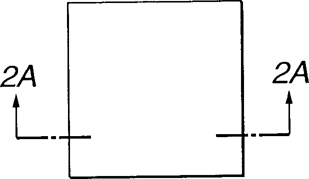
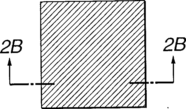
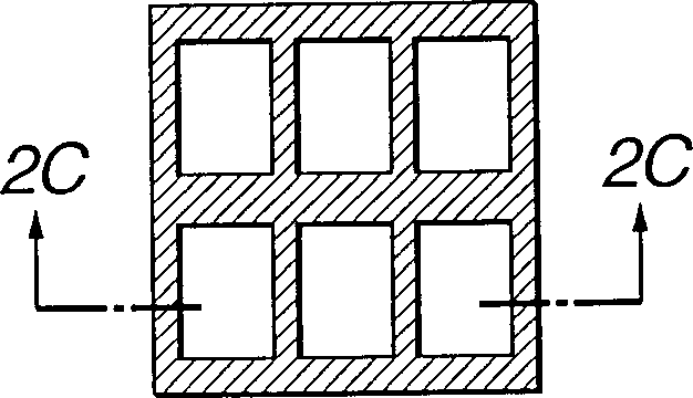
[0109]A black photoresist (V-259BK resist, available from Shinnittetsu Kagaku) ​​containing carbon black was applied to a glass substrate (#1737, available from Corning), and subjected to predetermined exposure treatments, development and flash drying , to prepare a black matrix pattern (partition wall) having a film thickness of 2 μm, and a rectangular opening with a size of 75 μm×225 μm. (preparation ink)

[0110] R, G and B inks having the following mixtures were prepared using an acrylic copolymer thermosetting component comprising the volume ratios shown below.

[0111] Thermohardening composition:

[0112] 50 parts by weight of methyl methacrylate

[0113] 30 parts by weight...

example 2

[0151] A color filter sample was manufactured as in Example 1 except that "CK-S171X resist" (available from Fujifilm Corporation) was used as a black matrix containing carbon black. After the plasma treatment step, the black matrix exhibits the following contact angles with respect to pure water.

[0152] Glass substrate surface: 5°

[0153] Black matrix substrate surface 128°

[0154] The surface average roughness (Ra) of the black matrix was 10.3 nm. The color filter swatch for this example does not show any color mixing, and there are no blank areas, with the colored parts appearing as flat surfaces. Example 3

example 3

[0155] Color filter samples were fabricated as in Example 1 except that argon gas was introduced during the dry etching process. After the plasma treatment step, the black matrix exhibits the following contact angles relative to pure water:

[0156] Glass substrate surface: 8°

[0157] Black matrix substrate surface 132°

[0158] The surface average roughness (Ra) of the black matrix was 6.8 nm. The color filter sample for this example does not show any color mixing and has no blank areas, the colored parts appear as flat surfaces. Example 4


PUM

PropertyMeasurementUnit
mean roughnessaaaaaaaaaa
surface roughnessaaaaaaaaaa

Abstract

An optical element comprising at least a plurality of pixels formed on a substrate and partition walls arranged respectively between adjacent pixels is manufactured by a method comprising steps of forming partition walls of a resin composition on a substrate, performing a dry etching process of irradiating the substrate carrying the partition walls formed thereon with plasma in an atmosphere containing gas selected at least from oxygen, argon and helium, performing a plasma treatment process of irradiating the substrate subjected to the dry etching process with plasma in an atmosphere containing at least fluorine atoms, and forming pixels by applying ink to the areas surrounding by the partition walls by means of an ink-jet system.

Description

technical field [0001] The present invention relates to a method of manufacturing an optical element for use as a color filter as an element of a color liquid crystal device commonly used in a color television set, a personal computer, etc., or a full-color display using an inkjet system having a plurality of light-emitting layers electroluminescent elements. Background technique [0002] The demand for liquid crystal displays, especially color liquid crystal displays, has been increasing in recent years to keep pace with the technological progress in the field of personal computers including portable personal computers. However, since color filters play an important role in the overall manufacturing cost, in order to further increase the demand, the cost of color liquid crystal displays, especially the cost of the color filters they include, has been further reduced. [0003] Various techniques have been proposed in an attempt to meet the above needs and meet the need to i...

Claims


Application Information

Patent Timeline
Patent Type & Authority Applications(China)
IPC IPC(8): G02B5/20G02F1/1335
CPCG02F1/133512G02B5/201G02F1/1335
Inventor 冈田健高野胜彦坂本淳一芝昭二岩田研逸谷内洋西田武人冈田良克
Owner CANON KK
Why Eureka
Try Eureka