
Constant pulsed light xenon lamp solar cell testing method

A solar cell and testing method technology, applied in the field of solar cell testing, can solve problems such as difficult optical path debugging, increased equipment volume, complex processing of reflective devices, etc.

Inactive Publication Date: 2003-11-19
XI AN JIAOTONG UNIV
View PDF3 Cites 16 Cited by
  • Summary
  • Abstract
  • Description
  • Claims
  • Application Information

AI Technical Summary

Problems solved by technology

Another example is the reflective device used in the test equipment SPI-SUNSIMULATOR 240A Photovoltaic Module Tester of Sprie Company in the United States, which is complicated to process and difficult to debug the optical path
And relying on increasing the distance between the light source and the test surface to achieve the method of illumination uniformity will greatly increase the volume of the equipment, such as the test equipment of Spectrolab company used by the National Aeronautics and Space Administration of the United States, the light source is 5 meters away from the test surface

Method used


Image

  • Constant pulsed light xenon lamp solar cell testing method
  • Constant pulsed light xenon lamp solar cell testing method
  • Constant pulsed light xenon lamp solar cell testing method

Examples


Embodiment 1

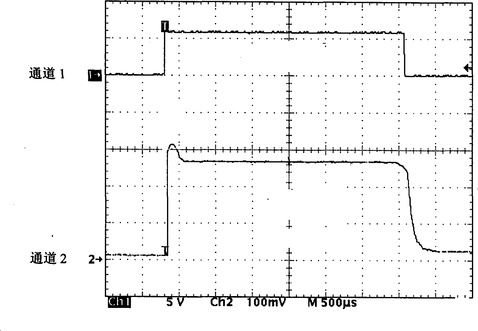
[0017] Example 1: Constant light intensity pulsed xenon lamp single solar cell test

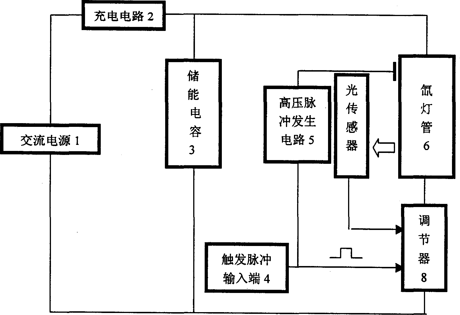
[0018] The core of this embodiment is to propose a new implementation of constant light intensity pulsed xenon lamp, the block diagram is as follows figure 1 shown, including:

[0019] AC power supply 1, charging circuit 2, energy storage capacitor 3, trigger pulse input terminal 4, high voltage pulse generating circuit 5, xenon lamp tube 6, light sensor 7, regulator 8.

[0020] The AC power supply 1 is connected to the energy storage capacitor 3 through the charging circuit 2, and the two ends of the energy storage capacitor 3 are connected to the xenon lamp tube 6 through the regulator 8 connected in series, and the trigger pulse input terminal 4 and the light sensor 7 are respectively connected to the regulator 8, The trigger pulse input terminal 4 is connected to the auxiliary electrode of the xenon lamp tube 6 through the high voltage pulse generating circuit 5 .

[0021] The AC power ...

Embodiment 2

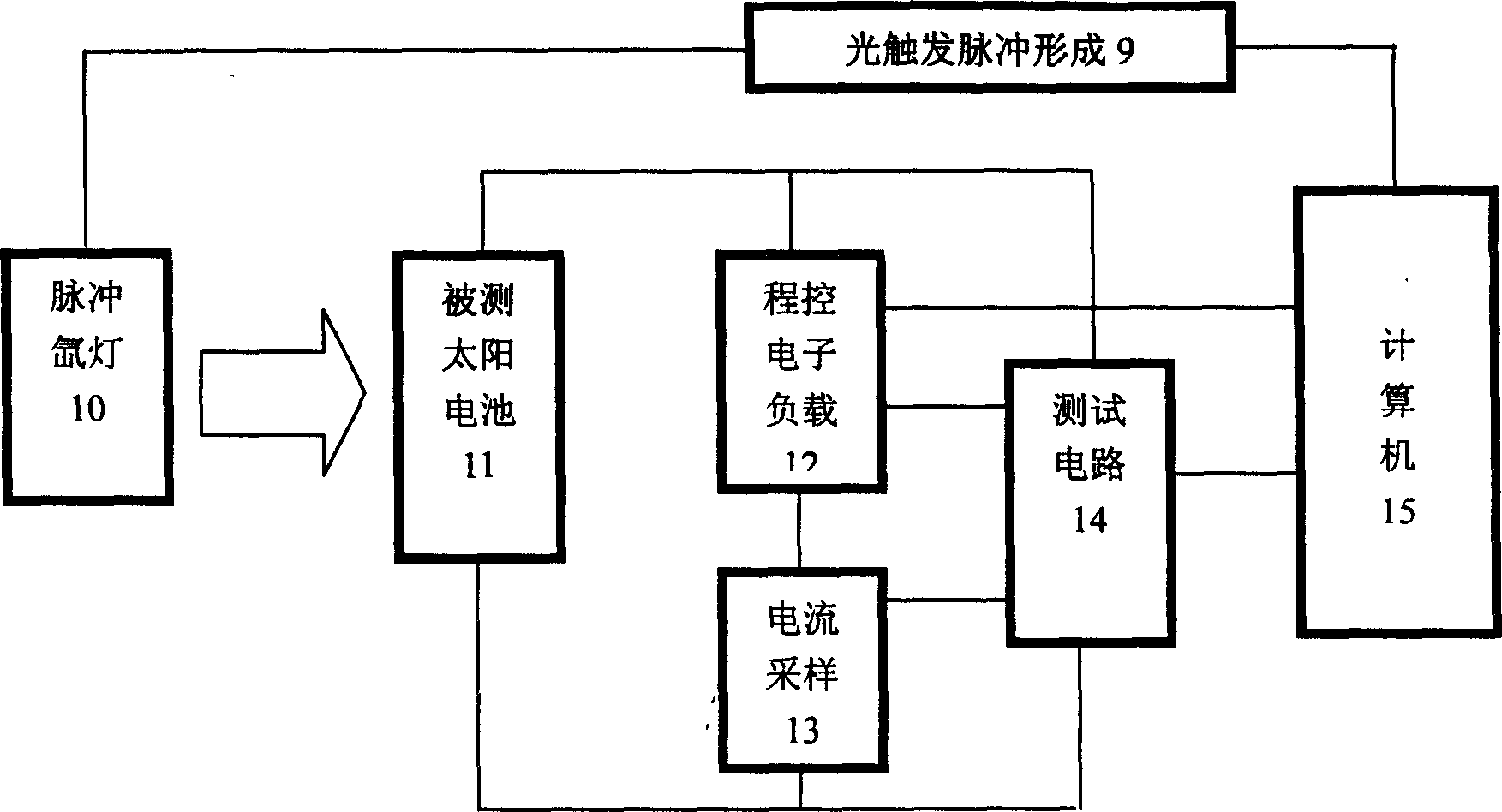
[0026] Example 2: Constant Light Intensity Pulse Xenon Lamp Solar Cell Module Test

[0027] In the solar cell assembly testing device prepared by the present invention, the pulse xenon lamp is about 2 meters away from the test plane of the solar cell assembly to be tested; four reflectors with adjustable angles are arranged in the testing device. By adjusting the angle and light reflection coefficient of the reflector, the light intensity uniformity of the 120CM×60CM test surface can meet the requirements.

[0028] Its structure and principle are as Figure 4 shown. Four reflectors 16 that can adjust the angle are installed in the test device. The light path from the constant light intensity pulse xenon lamp 10 directly to point A is shorter than the light path to point B, and the light intensity at point A is also large, but what hits point B is also the light reflected by point C of the reflector, two beams After the superposition of the light in the normal direction of p...


PUM


Abstract

A testing method utilizes light feedback and automatic control technique to modify camera used flash light or similar ones to be impulse xenon lamp with constant light strength in addition to conventional program-controlled electron load, testing circuit and computer. The light impulse with several milliseconds of constant light strength can be obtained at each flash of the light source and I-V curve data collection of solar energy battery can be finished by computer-controlled testing circuit within the period of single flash and to finalize test of solar battery electric parameter in several seconds. The method also can be used to test solar battery component as well as can be utilized to manufacture the testing device for both of one-body solar battery and solar battery component.

Description

1. Technical field [0001] The invention belongs to the field of solar battery testing, and relates to a single solar battery or solar battery module testing method and device thereof, in particular to a constant light intensity pulse xenon lamp solar battery testing method. 2. Background technology [0002] The key component of solar cell testing is the test light source (solar simulator). According to the results of document retrieval, there are two types of test light sources at home and abroad: constant bright type and pulse flash type. The constant bright test light source has the disadvantages of high energy consumption and easy heating, which will cause passive heating of the battery and affect the test results. For example, the computer test system for the solar battery simulation light source of Harbin-Korola Solar Power Company (Appendix 5 "Computer Test System for Solar Battery Simulation Light Source") Harbin-Korola Solar Power Company Sun Shixiong). However, th...

Claims


Application Information

Patent Timeline
IPC IPC(8): G01R31/36H02S50/15
CPCY02E10/50
Inventor 张克农王红雨
Owner XI AN JIAOTONG UNIV
Learn More