Testing method and system for measuring gas component concentration using spontaneous Raman scattering technology

A test system and concentration technology, applied in the direction of Raman scattering, material excitation analysis, etc., can solve the problems of inability to measure component concentration, difficult adjustment of optical path, difficult calibration, etc., achieve fast test speed, improve signal-to-noise ratio, and easy operation Effect

Inactive Publication Date: 2004-01-14
DALIAN INST OF CHEM PHYSICS CHINESE ACAD OF SCI
View PDF0 Cites 18 Cited by
  • Summary
  • Abstract
  • Description
  • Claims
  • Application Information

AI Technical Summary

Problems solved by technology

The disadvantages of this device are: it adopts a combination lens to collect signals, and it is not easy to adjust the optical path; this device can only obtain the yield of singlet oxygen, and cannot measure the concentration of other components, which has great limitations
[0005] The existing measurement methods and devices above all have various shortcomings and deficiencies to varying degrees. Some methods are cumbersome, some are not easy to calibrate, some can test low pressure, and large errors will be introduced when measuring slightly high pressure.

Method used


Image

  • Testing method and system for measuring gas component concentration using spontaneous Raman scattering technology
  • Testing method and system for measuring gas component concentration using spontaneous Raman scattering technology
  • Testing method and system for measuring gas component concentration using spontaneous Raman scattering technology

Examples


Embodiment 1

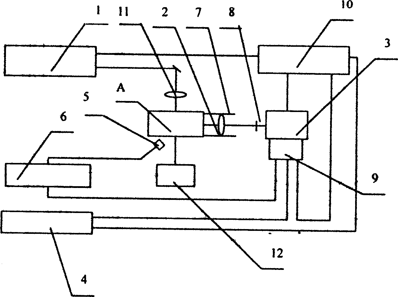
[0042] see figure 1 , the test device consists of a laser, a collection system, a detection system and a data processing system. The laser 1 is a linearly polarized laser. Before reaching the sample cell A, it passes through a lens 11 to collect the laser beam and strengthen its optical density; A device 12 for absorbing laser light is provided below to prevent laser light from scattering. The collection system is a lens 2, and the lens 2 is a biconvex lens, a plano-convex lens or a meniscus lens that can collect light beams; an extinction cylinder 7 is set on the outside of the lens 2; the detection system is a grating spectrometer 3 with an array detector ICCD 9, the grating There is a filter 8 in front of the spectrometer 3, and the grating of the grating spectrometer 3 can be adjusted, which can observe the Raman spectra of multiple components at the same time, and adjust the spectral range according to the different components of the sample material; the data processing s...

Embodiment 2

[0045] The following takes the performance parameter measurement of the singlet oxygen generator as an example to illustrate the use method of the device of the present invention.

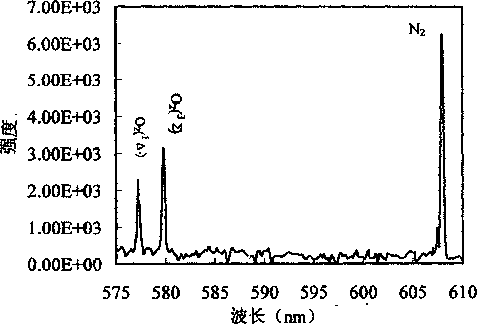
[0046] We use spontaneous Raman scattering spectroscopy to measure N 2 , O 2 (a 1 Δ)and O 2 (X 3 ∑) concentration, the same device was used to measure the O concentration for the first time. 2 ( 1 Δ) yield and chlorine utilization.

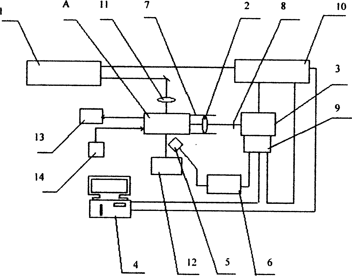
[0047] see figure 2 , because the gas pressure is low, the pump light power is required to be high, so a high-power pulsed laser is generally used, and a YAG laser is used in this embodiment. The sample cell A is the airflow delivery section of the singlet oxygen generator 14 (SOG), and the O 2 ( 1 Δ) The mixed gas flow is pumped away by the vacuum pump 13 at a certain rate to keep the gas in a negative pressure state. A window is opened on the airflow conveying pipe at the exit of SOG14, the laser light of YAG laser 1 is focused on the test point by the len...


PUM


Abstract

The present invention discloses the method and system for measuring the gas component by the spontaneous Raman dissemination process wherein the system comprises a laser, a collecting system, a detection system and a data processing system, the laser device sends linear polarization laser, the collecting system is a lens, the detecting system is a grating optical spectrum device with a ICCD array detector which can be used to regulate the optical spectrum of the sampled article. The invention can greatly increase the signal-to-noise ratio, and the detecting system can enable the grating and central wavelength to be regulated at any time according the requirement of the test, thus facilitating the acquisition of the Raman spectrum of the different components.

Description

technical field [0001] The present invention relates to a method for measuring the concentration of gas components and a measuring system using the method, in particular to a measuring method and system for measuring the concentration of gas components using spontaneous Raman scattering technology. Background technique [0002] Oxygen iodine chemical laser has been developed for 20 years, and its most critical component, the performance parameter measurement of singlet oxygen generator, has always been a concern of people. For the performance parameter test of oxygen iodine chemical laser, an accurate, convenient, A practical approach is necessary. O 2 ( 1 Δ) is the energy source of an oxygen-iodine chemical laser (COIL). The output power of oxygen iodine chemical laser is directly related to O 2 ( 1 Δ) is related to the yield, O 2 ( 1 Δ) is produced by the reaction of chlorine gas and chemical solution in a singlet oxygen generator (SOG), so O 2 ( 1 The yield of Δ)...

Claims


Application Information

Patent Timeline
Patent Type & Authority Applications(China)
IPC IPC(8): G01N21/65
Inventor 赵伟力多丽萍桑凤亭陈方王增强
Owner DALIAN INST OF CHEM PHYSICS CHINESE ACAD OF SCI
Why Eureka
Try Eureka