Method and its device for connection electric continuous electrolytic corrosion between metal belts

A technology of electrolytic corrosion and metal strip, applied in the direction of electrolysis process, electrolysis components, etc., can solve problems such as corrosion

Inactive Publication Date: 2004-02-11
NIPPON STEEL CORP
View PDF4 Cites 8 Cited by
  • Summary
  • Abstract
  • Description
  • Claims
  • Application Information

AI Technical Summary

Problems solved by technology

[0014] Therefore, in order to help solve the problems of the above-mentioned prior art, the present invention not only adopts the indirect energization continuous electrolytic corrosion technology that has not been practically used in the industry, but also helps to solve the existing indirect energization continuous electrolytic corrosion problems.

Method used


Image

  • Method and its device for connection electric continuous electrolytic corrosion between metal belts
  • Method and its device for connection electric continuous electrolytic corrosion between metal belts
  • Method and its device for connection electric continuous electrolytic corrosion between metal belts

Examples


Embodiment 1~5

[0088] The metal strip before electrolytic corrosion is cold rolled to the final plate thickness under the following conditions. After decarburization annealing, an annealing separator made of MgO is coated and dried on both sides of the surface, and further finishing annealing is performed. In the two surfaces, forsterite (Mg 2 SiO 4 ) film, coated with a tension-imparting film (phosphoric acid-based insulating film), it becomes a sintered grain-oriented silicon steel sheet, and becomes a grain-oriented silicon steel sheet with an etching pattern formed on the surface of one side. After removing the forsterite film and the tension-imparting film, the corrosion pattern of ferrite is exposed. In addition, since this tension-imparting film is an electrically insulating film, it can be used as an etching mask.

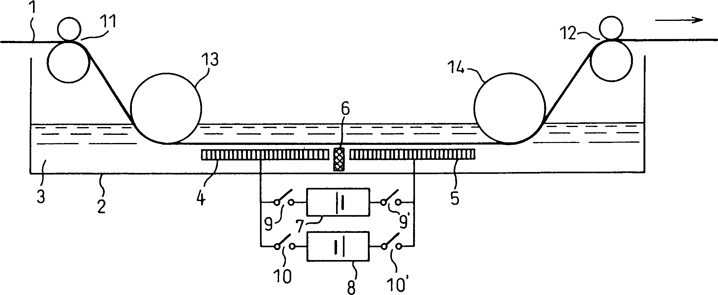
[0089] In the grain-oriented silicon steel sheet subjected to the above pretreatment, use figure 1 or image 3 The shown indirect energization type continuous electr...

Embodiment 6

[0104] Finished by cold rolling to a thickness of 0.23 mm, and subjected to finish annealing as a unidirectional electrical steel sheet, 0.3 mm wide corrosion patterns were formed on the steel sheet coated with an insulating film at intervals of 6 mm by laser irradiation, and then combined with ferrite The steel plate surface of the exposed part of the body faces each other, and the plate is passed through an electrolytic cell in which two electrodes of positive and negative electrodes are alternately arranged. Wherein, the electrolytic solution uses a sodium chloride aqueous solution with a concentration of 5%, and uses sodium hydroxide and hydrochloric acid to adjust the pH. Etching was performed by varying the pH, passing the plates in the pH 1 to pH 12 range.

[0105] The above-mentioned sample according to the present invention was taken out, the shape of the groove was confirmed, and grooves with an average depth of about 20 micrometers were formed. Table 2 shows the re...

Embodiment 7

[0109] It was finished by cold rolling to a thickness of 0.27mm, and was subjected to finishing annealing as a unidirectional electrical steel sheet. On the steel sheet coated with an insulating film, 0.3mm-wide corrosion patterns were formed by laser irradiation at intervals of 4mm. Facing the surface of the steel sheet having the ferrite exposed portion, the sheet is passed through an electrolytic cell in which two electrodes, negative and positive, are alternately arranged. Wherein, the electrolytic solution uses a sodium chloride aqueous solution with a concentration of 3%, and uses sodium hydroxide and hydrochloric acid to adjust the pH. Etching was performed by varying the pH, passing the plates in the pH 1 to pH 12 range.

[0110] When the groove shape was confirmed for the above sample, grooves with an average depth of about 15 micrometers were formed.

[0111] Table 3 shows the results of investigating the amount of iron deposited during the treatment in the electrol...


PUM

PropertyMeasurementUnit
thicknessaaaaaaaaaa

Abstract

The present invention provides a method for indirect-electrification-type continuous electrolytic etching of a metal strip suitable for producing a low-core-loss, grain-oriented silicon steel sheet not susceptible to the deterioration of core loss after stress-relief annealing, and an apparatus for the indirect-electrification-type continuous electrolytic etching. It is a method for indirect-electrification-type continuous electrolytic etching of a metal strip and an apparatus for the same for continuously forming grooves by indirect-electrification-type electrolytic etching on a metal strip on which an etching mask is formed in etching patterns on one or both surfaces, wherein: plural electrodes of an A series and a B series are arranged alternately, at least in a pair, in said order in the travelling direction of the metal strip so that they face the surface to be etched of the metal strip on which the etching patterns are formed; the space between the metal strip and the group of the electrodes is filled with an electrolyte; and voltage is applied across the A series and B series electrodes. Desirably, (I) a voltage application wherein an A series electrode becomes a cathode for a time period M of 3 to 10 msec. and (II) a voltage application wherein the A series electrode becomes an anode for a time period N of 4xM to 20xM msec. are repeated alternately across the A series and B series electrodes.

Description

technical field [0001] The present invention relates to an indirect energization type continuous electrolytic corrosion method and an indirect energization type continuous electrolytic corrosion device for metal strips, in particular to an iron core suitable for manufacturing power transformer iron cores, which is less prone to iron loss after stress relief annealing Indirect energization type continuous electrolytic corrosion method and indirect energization type continuous electrolytic corrosion device for deteriorated low iron loss unidirectional silicon steel sheet and metal strip. Background technique [0002] The unidirectional electromagnetic steel sheet that has been put into practical use is easy to magnetize in the rolling direction of the steel sheet, and is mainly used in electrical equipment such as transformers. If the magnetic domain is refined by introducing local deformation or forming grooves in the steel plate, the eddy current flowing through the cross se...

Claims


Application Information

Patent Timeline
Patent Type & Authority Applications(China)
IPC IPC(8): C25F3/06C25F3/14C25F7/00
CPCC25F7/00C25F3/06C25F3/14
Inventor 茂木尚野村成彦古贺重信藤仓昌浩山崎修一
Owner NIPPON STEEL CORP
Why Eureka
Try Eureka