

Magne to electric composite material and manufacturing method thereof
A technology of magnetoelectric composite materials and piezoelectric composite materials, which is applied in the selection of device materials, the manufacture/assembly of magnetostrictive devices, and the manufacture/assembly of piezoelectric/electrostrictive devices to reduce losses and improve conversion efficiency. , the effect of high magnetoelectric coupling effect
- Summary
- Abstract
- Description
- Claims
- Application Information
AI Technical Summary
Problems solved by technology
Method used
Image

Examples
Embodiment 1
[0025] Embodiment 1. The magnetoelectric composite material of the present invention.
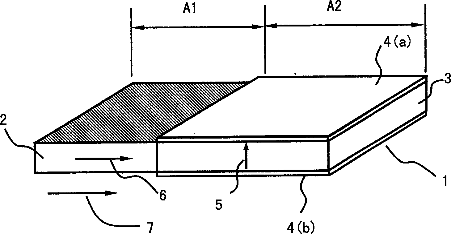
[0026] Such as figure 1 As shown, the magnetoelectric composite material rectangular sheet 1 is composed of the magnetostrictive composite material rectangular sheet 2 located in the A1 area and the piezoelectric composite material rectangular sheet 3 located in the A2 area. Wherein, there are planar electrodes 4 (a), 4 (b) for output voltage on the surface of the piezoelectric composite material rectangular sheet 3, and the polarization direction of the piezoelectric composite material A2 area is along the thickness direction, such as figure 1 Indicated by the middle arrow 5; in the rectangular sheet 2 of the magnetostrictive composite material, the magnetic domains have a preferred orientation along the length direction, such as figure 1 Shown by middle arrow 6.
[0027] Magnetostrictive composite rectangular sheet 2 is a composite material formed by compounding epoxy resin and Terfenol...
Embodiment 2
[0031] Example 2. Preparation of the magnetoelectric composite material of Example 1.
[0032] Crush the Terfenol-D block material with orientation, grind it in an ethanol solvent, take it out and dry it, and sieve it to obtain particles with an average particle size of 100 microns for use; similarly, crush the PZT block material , grind, take out and sieve to obtain particles with an average particle size of 60 microns for later use.
[0033]Mix Terfenol-D particles with low-viscosity epoxy resin and pour them into a rectangular die; apply a DC magnetic field along the depth direction of the die, so that the magnetic field strength in the center of the die is 1.5kOe; then, apply precompression stress molding, Take out the pre-pressed embryo block and set aside.
[0034] Stir and mix PZT granules and low-viscosity epoxy resin fully, pour into a rectangular die, apply pre-compression stress to shape, and take out the pre-compression green block for use.
[0035] The formula ...
Embodiment 3
[0042] Embodiment 3. The magnetoelectric composite material of the present invention.
[0043] The structure of the magnetoelectric composite material in this embodiment is similar to the structure of the magnetoelectric composite material in Example 1. It is a rectangular sheet as a whole, with a sheet length, sheet width and sheet thickness extending from one end to the other end along the length direction, and The rectangular piece of magnetoelectric composite material is divided into two regions A1 and A2 along the length direction, the region A1 is made of magnetostrictive material, and the region A2 is made of piezoelectric material. The basic difference between the magnetoelectric composite material of this embodiment and the magnetoelectric composite material of Example 1 is that: the magnetostrictive material in A1 area is Terfenol-D, the piezoelectric material in A2 area is PZT piezoelectric ceramics, A1 area and The A2 area is bonded with epoxy resin adhesive. Othe...
PUM
| Property | Measurement | Unit |
|---|---|---|
| The average particle size | aaaaa | aaaaa |
| The average particle size | aaaaa | aaaaa |
Abstract
Description
Claims
Application Information