
Wavelength control using dither modulation and feedback

A technology of high-frequency vibration and servo control, applied in multiplexing communication, wavelength division multiplexing system, electromagnetic wave transmission system, etc., can solve the problems of reducing data modulation rate, loss, non-use, etc., and increase batch output Effect

Inactive Publication Date: 2004-06-30
INT BUSINESS MASCH CORP
View PDF0 Cites 10 Cited by
  • Summary
  • Abstract
  • Description
  • Claims
  • Application Information

AI Technical Summary

Problems solved by technology

This problem places fundamental constraints on the design of future WDM networking systems
[0004] A second, related problem arises from the fact that the DC modulation of the data onto the semiconductor laser diode induces two effects that can lead to a rapid shift in the center wavelength of the laser immediately after the start of the laser pulse, these are (1 ) frequency chirp and (2) relaxation oscillation
Avoiding both of these effects requires non-standard and expensive lasers, external modulators (which are lossy and increases cost), or driving the laser with less than its maximum power capacity (which reduces link budget and distance)
Reducing the data modulation rate is also helpful, but not typically used in multi-gigabit laser links

Method used


Image

  • Wavelength control using dither modulation and feedback
  • Wavelength control using dither modulation and feedback
  • Wavelength control using dither modulation and feedback

Examples


Embodiment Construction

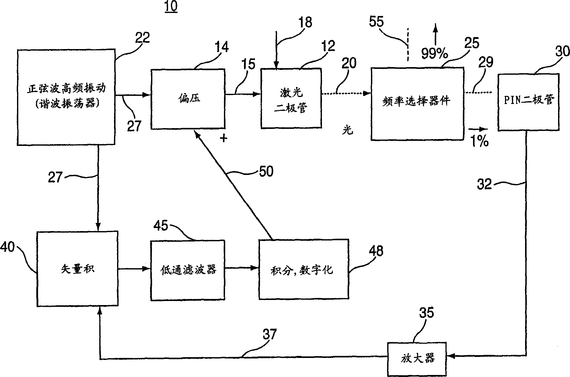
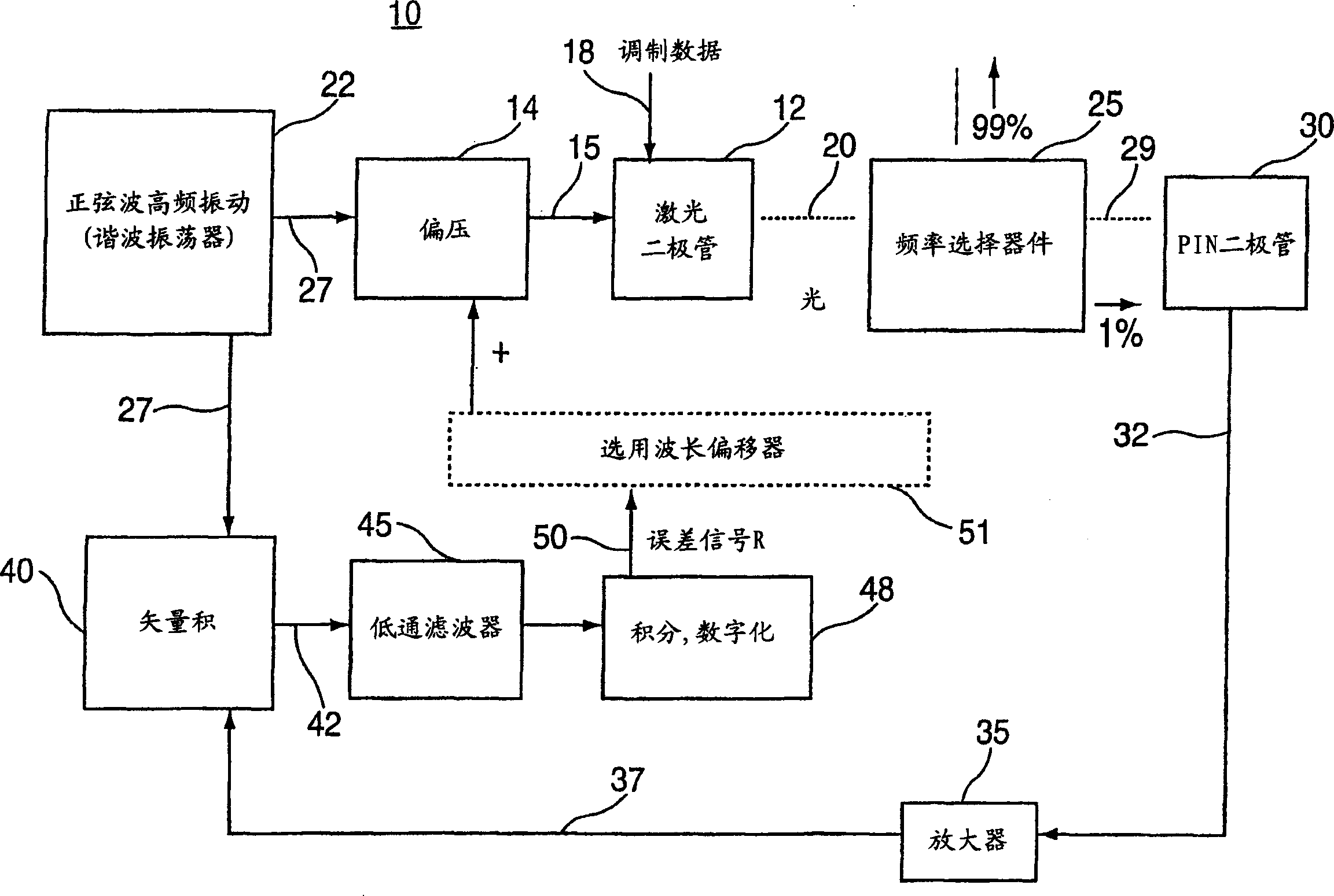
[0030]The present invention is a novel servo control system implemented for an optical system including a light source such as a laser, and a frequency selective device such as a bandpass filter. The servo control system, referred to herein as a "Wavelength Locked Loop" or "Lambda Locked Loop" (since the symbol Lambda is commonly used to represent wavelength), implements dither modulation to continuously adjust the electromagnetic signal source , in order to track the center of a frequency selective device such as an optical filter passband, the electromagnetic signal source is characterized by including a peak frequency spectrum or a peak center wavelength, such as a laser. In this way, the optimal power of the signal is transmitted and the system transmission paths are optimally used.

[0031] The basic operating principle of a wavelength locked loop (WLL) is now described with reference to FIG. Circuit 14 is driven by a bias voltage 15 and modulated data 18 from a data sou...


PUM


Abstract

A wavelength-locked loop servo-control circuit and methodology that enables real time mutual alignment of an electromagnetic signal having a peaked spectrum function including a center wavelength and a wavelength selective device implementing a peaked passband function including a center wavelength, in a system employing electromagnetic waves. The circuit comprises a mechanism for applying a dither modulation signal at a dither modulation frequency to the electromagnetic signal, and inputting the dither modulated electromagnetic signal to the wavelength selective device; a mechanism for converting a portion of the dither modulated electromagnetic signal to an electric feedback signal; a mechanism for continuously comparing the feedback signal with said dither modulation signal and generating an error signal representing a difference between a frequency characteristic of the feedback signal and a dither modulation frequency; and a mechanism for adjusting the peaked spectrum function of the electromagnetic signal according to the error signal. The center wavelength of the electromagnetic signal and the wavelength selective device center wavelength become aligned when the frequency characteristic of the feedback signal is two times the dither modulation frequency.

Description

technical field [0001] The present invention relates generally to systems for generating and processing electromagnetic signals in the radio frequency, microwave and optical spectrum, and in particular to novel servo control circuits for using such electromagnetic signals for such systems, which apply the Principle of wavelength-locked loop to optimize signal power and transmission bandwidth. Background technique [0002] Wavelength Division Multiplexing (WDM) and Dense Wavelength Division Multiplexing (DWDM) are lightwave application technologies that enable multiple wavelengths (colors of light) to enter the same fiber in parallel, with each wavelength potentially assigned its own data diagnostics. Currently, WDM and DWDM products combine many different data links over a single pair of fibers by remodulating the data onto a set of lasers tuned to very specific wavelengths (within 0.8nm tolerance, according to industry standard ). On current products, up to 32 wavelengths...

Claims


Application Information

Patent Timeline
Patent Type & Authority Applications(China)
IPC IPC(8): H04B1/04H04B10/00H04B10/25H04J14/00H04J14/02
CPCH04B10/572H04B10/506H01S5/06832H04B10/00H04B10/25
Inventor 卡西莫·M·德库萨蒂斯劳伦斯·雅各博维茨
Owner INT BUSINESS MASCH CORP
Learn More