Fibre-optical probe with excellent vibration characteristic and producing method thereof

A technology of optical fiber probe and vibration characteristics, which is applied in the field of scanning optical microscopy imaging, can solve problems such as failure to work, system failure to work well, and difficulty in forming a fundamental frequency vibration frequency curve, etc., to achieve increased costs, no transmission efficiency, The effect of excellent vibration characteristics

Inactive Publication Date: 2004-07-07
UNIV OF SCI & TECH OF CHINA
View PDF0 Cites 12 Cited by
  • Summary
  • Abstract
  • Description
  • Claims
  • Application Information

AI Technical Summary

Problems solved by technology

However, since the fiber optic probe glued to the front end of a vibrating arm of a quartz tuning fork has a very long pigtail for transmitting near-field optical signals to the photomultiplier tube, this will inevitably ...

Method used


Image

  • Fibre-optical probe with excellent vibration characteristic and producing method thereof
  • Fibre-optical probe with excellent vibration characteristic and producing method thereof
  • Fibre-optical probe with excellent vibration characteristic and producing method thereof

Examples


Embodiment Construction

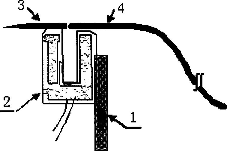
[0017] 1. Pre-production of fiber optic probes

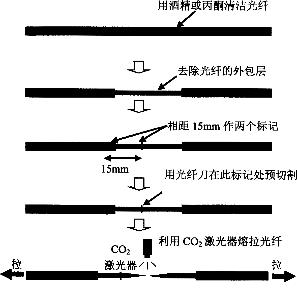
[0018] The following steps are used in the pre-production of fiber optic probes: ①melting or chemical etching or corrosion after melting to form a micro-probe; ②coating a layer of metal film on the micro-probe to form a nanometer-sized optical aperture at the tip of the probe . What the present invention specifically adopts is the method of laser heating melting drawing, and the optical fiber melting drawing machine used is the model P-2000 optical fiber melting drawing machine produced by Sutter Instrument Company.

[0019] First, cut a section of single-mode optical fiber with a length of about 20cm and a diameter of 0.125mm, and use a mechanical fiber peeler to strip the outer cladding of the optical fiber for about 30mm in the middle; use an oil-based pen at a distance of about 3mm from the starting point of the end where the cladding is removed. The first mark (this mark is located on the outer cladding of the fiber), and ...


PUM


Abstract

The present invention is an optical fiber probe having excellent vibration property and its manufacturing method relating to the scanning optical micro-imaging technology, particularly being directed to the imaging members provided in the scanning type of the near-field optical microscope and their manufacturing method in the near-field optical experiment technology. In this method, the optical fiber probe of prior art is cut off into a shape of short needle to make it face and be coupled with the end face of another long optical fiber connected to an photoelectric detector, said optical fiber short needle being placed on a vibrating arm of a vibrating member (e.g. quartz tuning fork) and said long optical fiber being placed on a fixed arm of the vibrating member; its manufacturing steps comprises preprocessing, marking position, pre-cutting, needle shaping, fixing optical fiber needle, cutting off it into short needle, coupling it with long optical fiber, etc. This invention has the novel structure of non-contacting type of short probe and the basic frequency of the vibrating frequency of the vibrating member is not interfered, so that the optical fiber probe has the excellent vibrating property, and the optical transmitting efficiency is not affected very much, the manufacturing cost is not increased. The invention can be used readily in the current near-field optical microscopes.

Description

Technical field: [0001] The invention relates to a scanning optical microscopic imaging technology, in particular to an imaging component provided by a scanning near-field optical microscope in the near-field optical experimental technology and a manufacturing method thereof. Background technique: [0002] Near-field optical microscopy (abbreviated as NSOM) performs optical measurements at distances much smaller than a wavelength (i.e., in the near-field) to obtain super-diffraction-limited spatial resolution. The current near-field optical microscope uses a melted or corroded optical fiber, and coats it with a metal film to form an optical aperture with a diameter of 10nm to 100nm at the end as an optical probe, which can be installed on a precision displacement and scanning probe. On the piezoelectric ceramic material, combined with the highly accurate feedback control provided by atomic force microscopy (AFM), the optical probe is very precisely controlled at a height of ...

Claims


Application Information

Patent Timeline
IPC IPC(8): G01Q60/22
Inventor 王沛蔡定平鲁拥华谢建平明海
Owner UNIV OF SCI & TECH OF CHINA
Why Eureka
Try Eureka