Method of manufacturing glass optical device
A technology of optical components and manufacturing methods, which is applied in the direction of glass pressing, glass manufacturing equipment, glass molding, etc., can solve the problems of inability to prevent perforation, cracks, turbidity of glass optical components, and inability to prevent tiny welding, etc., to achieve extended Effects of life, reduction in removal frequency of regeneration, and prevention of damage to the molding surface
- Summary
- Abstract
- Description
- Claims
- Application Information
AI Technical Summary
Problems solved by technology
Method used
Image
Examples
Embodiment 1
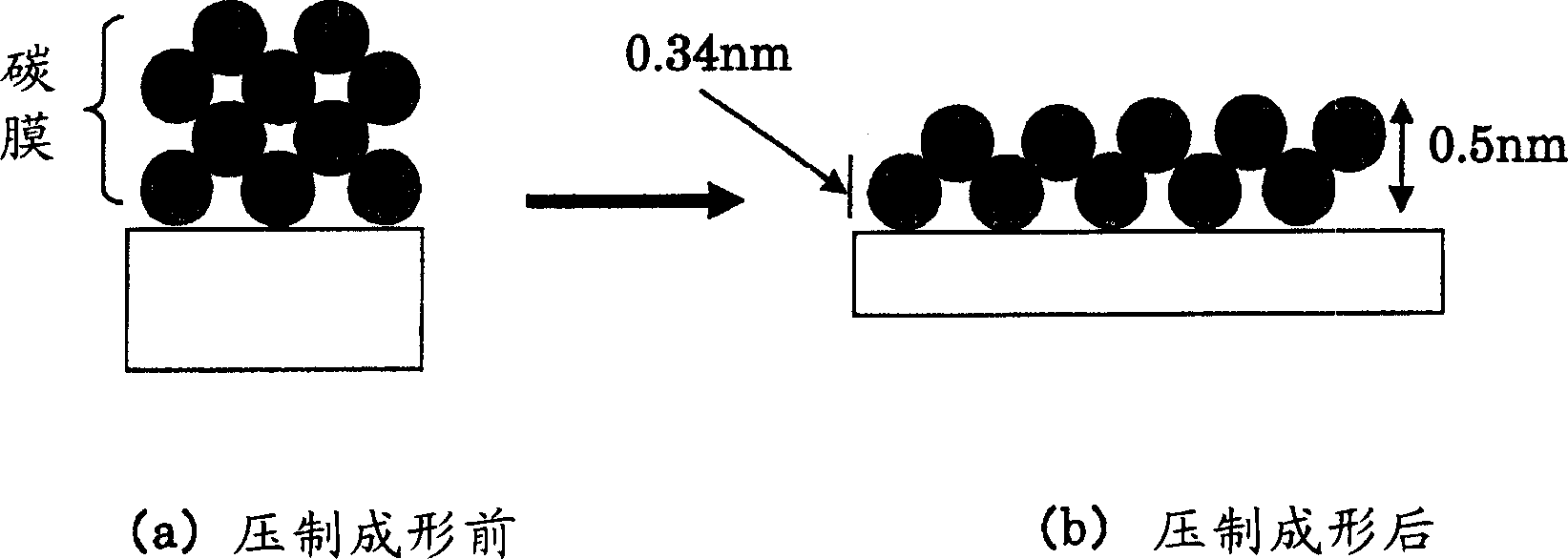
[0178] Prepare the glass blank for molding, and shape it into a spherical shape of 4.5mmφ in advance (borate glass containing alkali, surface free energy after cleaning: 65mJ / m 2 ). The blank is pressed into image 3 The shown biconvex lens has a diameter of 7.5 mmφ, a radius of curvature of the first surface of 7 mm, a radius of curvature of the second surface of 5 mm, and a thickness of a thin plate (coba) of 0.7 mm. At this time, it was confirmed that the portion with the largest surface area expansion was preliminarily formed as a peripheral flat portion by press forming, and it was confirmed that S(L) / S(PF)=5.2 at this portion. From this, the film thickness of the carbon film formed on the glass material was found to satisfy 0.5×5.2≦T≦10 (nm).
[0179]Here, a carbon film with a film thickness of 4.5 nm was formed on a glass blank by vapor deposition. The measurement of the thickness of the carbon film was carried out according to ESCA. In order to make the content of ...
Embodiment 2
[0192] Using the same glass material as in Example 1, a carbon film was formed by pyrolysis of high-purity acetylene gas to obtain a glass material having a carbon film with a film thickness of 4.5 nm (measured by ESCA). The device used for film formation is a CVD device. Exhaust the inside of the glass bell jar with a vacuum pump to a vacuum of 0.5 torr or below, heat and maintain at 480°C. The degree of vacuum was maintained at 160 torr by evacuating with a vacuum pump while introducing nitrogen gas into the glass bell jar. After evacuating for 30 minutes, the introduction of nitrogen gas was stopped. After evacuating the inside of the glass bell jar to 0.5torr or less with a vacuum pump, acetylene gas was introduced at 210torr for 210 minutes to form a carbon film on the glass blank.
[0193] The hydrogen content in the surface layer (from the surface to a depth of 500 nm) of the glass blank for molding was analyzed by ESCA, and the increase in the hydrogen content due to ...
Embodiment 3~13
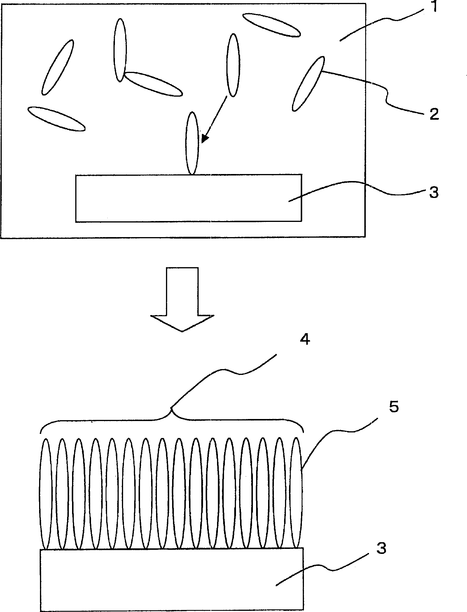
[0195] Except for changing the glass material for forming, the film-forming method of the carbon film, the film thickness of the carbon film, etc. according to Tables 1 to 3, the glass material for forming the carbon film was hit 5000 times in the same mold in the same manner as in Example 1. times for continuous pressing. However, Examples 7 and 8 are examples in which a self-assembled film was formed instead of a carbon film.
[0196] When the appearance of the optical elements obtained by press molding was observed, as shown in Tables 1 to 3, none of them had cloudiness, white cloudiness, or cracks, and the appearance quality was good or excellent.
[0197] Requirements
[0198] Requirements
[0199] Requirements
PUM
| Property | Measurement | Unit |
|---|---|---|
| thickness | aaaaa | aaaaa |
| thickness | aaaaa | aaaaa |
| thickness | aaaaa | aaaaa |
Abstract
Description
Claims
Application Information
 - R&D
- Intellectual Property
- Life Sciences
- Materials
- Tech Scout
- Unparalleled Data Quality
- Higher Quality Content
- 60% Fewer Hallucinations
Browse by: Latest US Patents, China's latest patents, Technical Efficacy Thesaurus, Application Domain, Technology Topic, Popular Technical Reports.
© 2025 PatSnap. All rights reserved.Legal|Privacy policy|Modern Slavery Act Transparency Statement|Sitemap|About US| Contact US: help@patsnap.com


