High speed photoelectric phase control array two dimension laser beam scanner

A two-dimensional laser and beam scanning technology, applied in the direction of instruments, optics, nonlinear optics, etc., can solve the problems of limited deflection range, large voltage change, and limited scanning accuracy, and achieve stable and reliable integration, no mechanical movement, and scanning fast effect

Inactive Publication Date: 2004-12-15
SHANGHAI INST OF OPTICS & FINE MECHANICS CHINESE ACAD OF SCI
View PDF0 Cites 16 Cited by
  • Summary
  • Abstract
  • Description
  • Claims
  • Application Information

AI Technical Summary

Problems solved by technology

Most of the commonly used two-dimensional beam scanners use the principle of electromechanical scanning, which is an analog type of scanning. The disadvantage is that it is affected by the accuracy of mechanical transmission, the scanning accuracy is limited, and the degree of miniaturization is low.
Another type of electro-optic control liquid crystal grating digital deflector developed in recent years has been more practical, but its deflection range is very limited, and its use in the fields of laser communication, laser radar and tracking and targeting technology is limited
[0003] The optical phased array beam scanner obtains the required deflection pointing by controlling the phase of each phased unit, prior art [1-2] ([1] see: James A, Mark Lasher, Yeshaiahn Fainman et al, 'A PLZT-based dynamic diffractive optical element for high speed, random-access beaming steering'. [C]Proc.SPIE, 1997, 3131:124-131. [2]See: James A.Thomas and Yeshaiahu Fainman.'Optimal cascade operation of opticalphased-array beam deflectors.') all use diffractive optical elements (DOE) to realize the scanning and deflection of the beam. Due to the small size of the phase control unit, the production p...

Method used


Image

  • High speed photoelectric phase control array two dimension laser beam scanner
  • High speed photoelectric phase control array two dimension laser beam scanner
  • High speed photoelectric phase control array two dimension laser beam scanner

Examples


Embodiment Construction

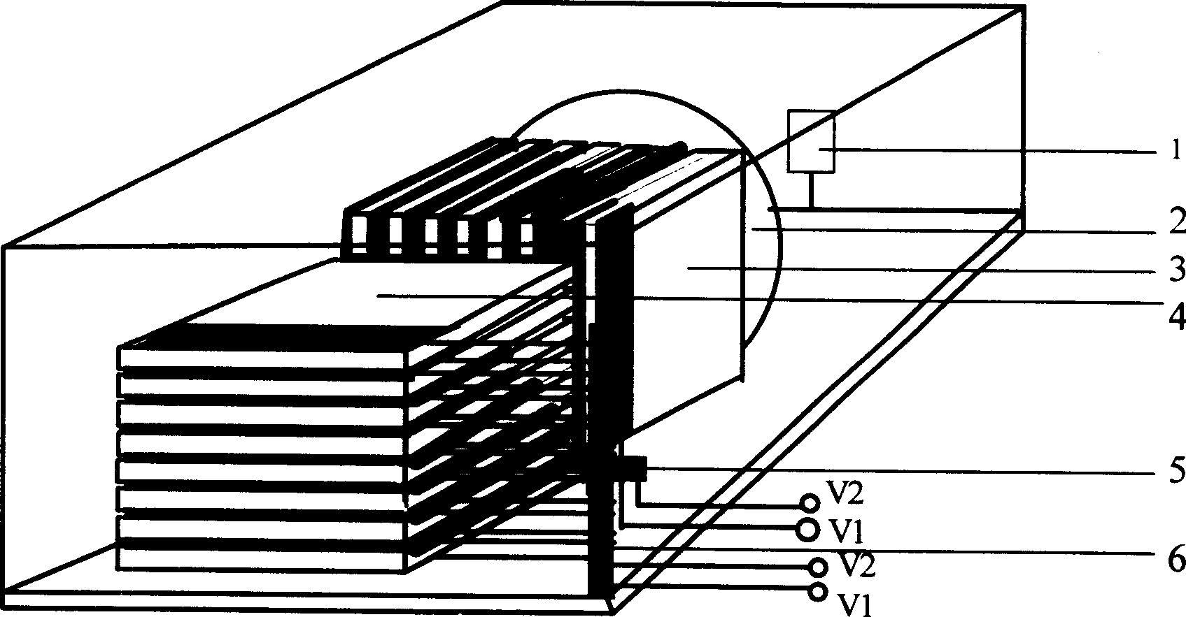
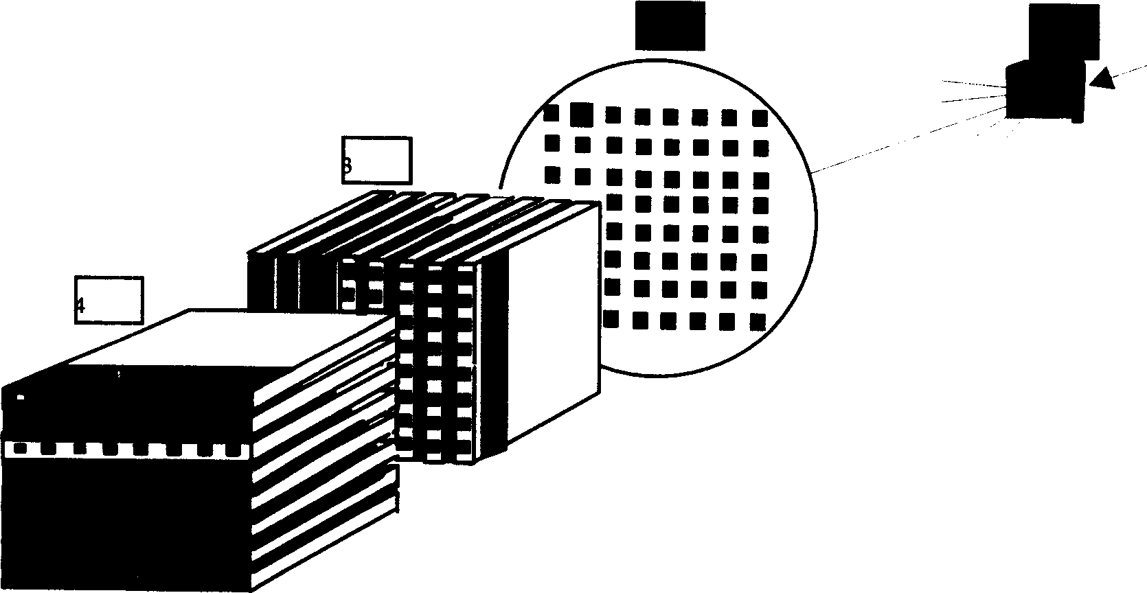
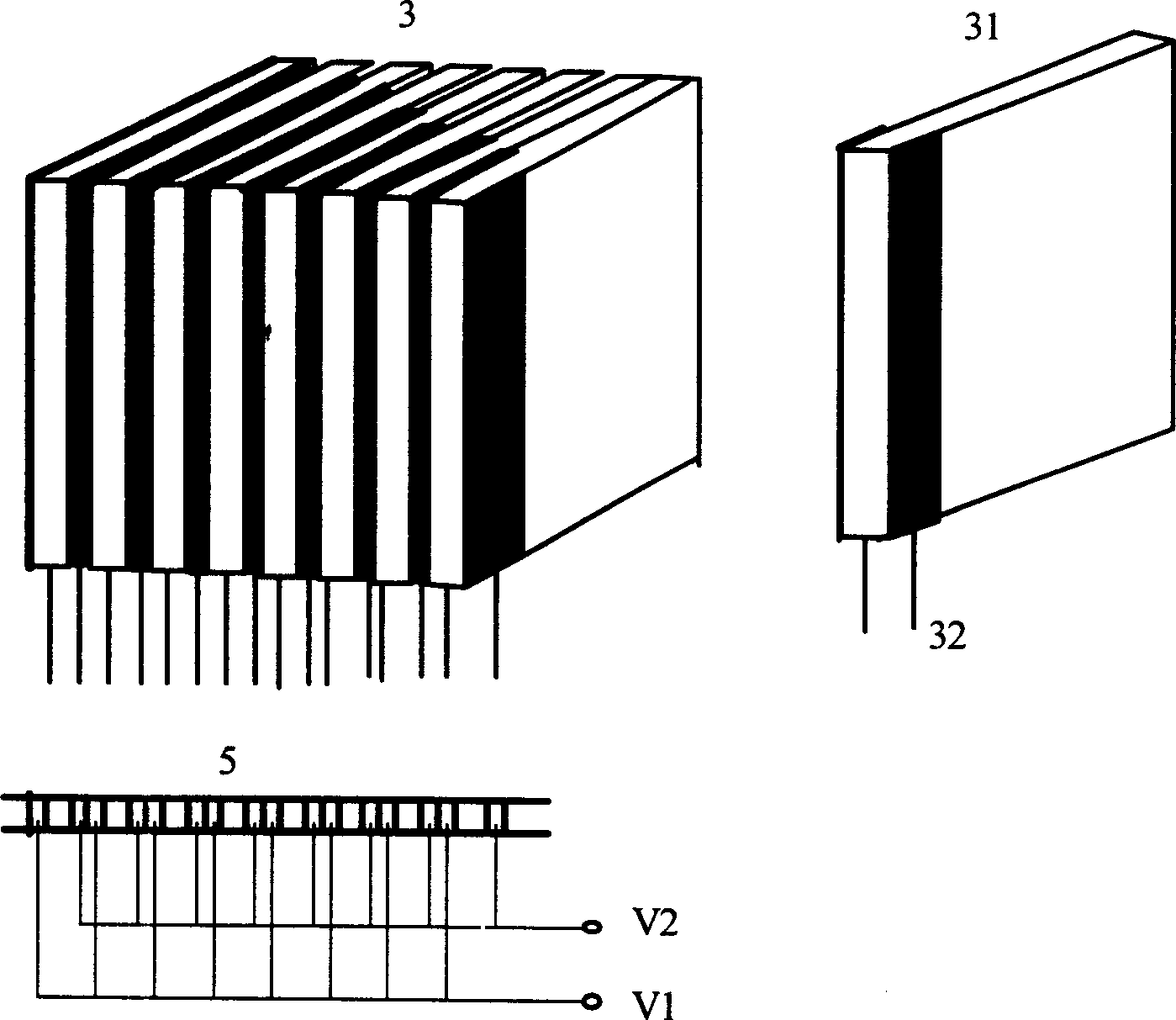
[0030] see first figure 1 , figure 1 It is the basic structure diagram of the present invention, and it can be seen from the figure that the composition of the high-speed electro-optic phased array two-dimensional laser beam scanner of the present invention is: along the direction of beam advancement, it includes in sequence; a plane diffraction grating 1, a collimating lens 2, and a horizontal scanning assembly 3 , the vertical scanning assembly 4, and the electrode socket 5 for inserting the horizontal scanning assembly 3 and the electrode socket 6 for inserting the vertical scanning assembly 4; the plane diffraction grating 1 is located on the focal plane of the collimating lens 2; The horizontal scanning assembly 3 described above is a crystal plate array composed of a plurality of lithium niobate crystal plates 31 with the same structure cut along the optical axis direction, and each lithium niobate crystal plate 31 is sequentially provided with short To the long electro...


PUM


Abstract

The 2D laser beam scanner consists of planar diffraction grating, collimating lens, horizontal scanning assembly on a socket, and vertical scanning assembly on a socket successively arranged in the light beam forward direction. The planar diffraction grating is in the focus plane of the collimating lens. The horizontal scanning assembly is one crystal plate array comprising several lithium niobate crystal plates in the same cutting structure and arranged in the optical axle direction, and the lithium niobate crystal plates have electrodes in sockets and in the equi-different lengths. The vertical scanning assembly has the same structure as the horizontal one but in vertical direction. The present invention has the features of fast scanning speed, high precision, no mechanism motion, simple structure, high stability and reliability and certain integration level.

Description

technical field [0001] The invention relates to a laser beam scanner, in particular to a high-speed electro-optic phased array two-dimensional laser beam scanner. Its main components are diffraction gratings and two vertically placed one-dimensional crystal flat modulation arrays. Changing the voltage of the modulation arrays can realize two-dimensional scanning of the beam. It is mainly used in laser radar, laser communication, laser 3D display and aiming tracking. and other technical fields. Background technique [0002] Laser beam scanning system has important applications in the fields of laser radar, laser communication, laser 3D display and aiming and tracking, and is a hot spot of current research. There are two types of laser beam scanners: analog type (continuously variable scanning angle) and digital type (fixed minimum offset angle). Most of the commonly used two-dimensional beam scanners use the principle of electromechanical scanning, which is an analog type o...

Claims


Application Information

Patent Timeline
IPC IPC(8): G02F1/29
Inventor 万玲玉刘立人张明丽孙建锋
Owner SHANGHAI INST OF OPTICS & FINE MECHANICS CHINESE ACAD OF SCI
Why Eureka
Try Eureka