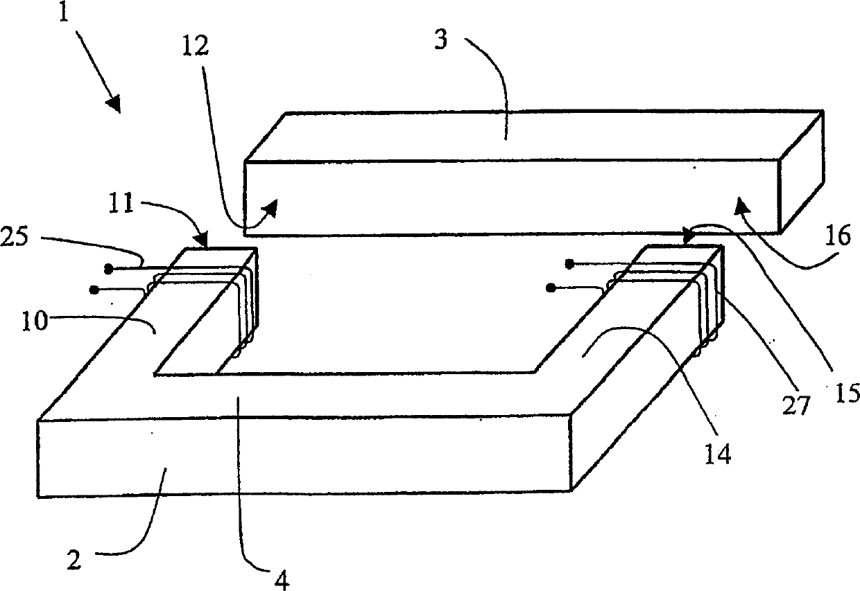
Bulk amorphous metal inductive device
An induction device, amorphous technology, applied to magnetic objects, inductors with magnetic cores, parts of transformers/inductors, etc., can solve problems such as impractical large devices, increased ohmic losses, and low magnetic induction values, and achieve Effects of Difficulty and Complexity Removal
- Summary
- Abstract
- Description
- Claims
- Application Information
AI Technical Summary
Problems solved by technology
Method used
Image
Examples
example 1
[0091] Preparation and Electromagnetic Test of Amorphous Metal Rectangular Prism
[0092] About 25mm wide and 0.022mm thick Fe 80 B 11 Si 9A strip of ferromagnetic amorphous metal is wound around a rectangular mandrel or bobbin having dimensions of approximately 25 mm wide and 60 mm long. About 1300 turns of ferromagnetic amorphous metal strip were wound around a mandrel or bobbin, resulting in a rectangular core form with internal dimensions of about 25mm wide and 60mm long and a build thickness of about 30mm. Anneal the core / bobbin assembly in a nitrogen atmosphere. The annealing included: 1) heating the assembly to 365°C; 2) maintaining the temperature at about 365°C for about 2 hours; and 3) cooling the assembly to ambient temperature. A rectangular, wound, amorphous metal core is removed from the core / bobbin assembly and then dipped in a low viscosity thermally activated epoxy that impregnates and infiltrates the adjacent laminated structure space between. The epoxy...
example 2
[0100] High-frequency behavior of low-loss bulk amorphous metal components
[0101] The core loss data included in Example 1 above were analyzed using conventional nonlinear regression methods. Certainly, by Fe 80 B 11 Si 9 The core loss of a bulk amorphous part composed of amorphous metal strips can be mainly defined by a function of the form
[0102] L(B max , f)=c 1 f(B max ) n +c 2 f q (Bmax) m coefficient c 1 and c 2 Appropriate values for the sum indices n, m and q are chosen to define an upper limit for the magnetic loss of the bulk amorphous metal part. Table 5 lists the measured losses for the components in Example 1 and the losses predicted by the above formula, each loss measured in watts per kilogram. Utilization factor c 1 = 0.0074 and c 2 = 0.000282 and exponent n=1.3, m=2.4 and q=1.5 calculated as f(Hz) and B max Prediction loss as a function of (Tesla). The measured loss of the bulk amorphous metal part in Example 1 is less than the correspon...
example 3
[0105] Fabrication of Amorphous Metal Trapezoidal Prisms and Sensors
[0106] About 25mm wide and 0.022mm thick Fe 80 B 11 Si 9 Ferromagnetic amorphous metal strips were cut into lengths of approximately 300 mm. About 1300 layers of cut ferromagnetic amorphous metal strips were laminated to form a rod about 25 mm wide and 300 mm long with a build thickness of about 30 mm. The rods were annealed in a nitrogen atmosphere. The annealing included: 1) heating the rod to 365°C; 2) maintaining the temperature at about 365°C for about 2 hours; and 3) cooling the rod to ambient temperature. The rods were vacuum impregnated with an epoxy resin solution and cured at 120°C for about 4.5 hours. The weight of the resulting laminated, epoxy-bonded, amorphous metal rod was approximately 1300 g.
[0107] The rod was cut using a 1.5 mm thick cutting blade to form four substantially identical trapezoidal prism components. At each end of each prism a mating surface. The mating faces are ...
PUM
 Abstract
Description
Claims
Application Information
 - R&D
- Intellectual Property
- Life Sciences
- Materials
- Tech Scout
- Unparalleled Data Quality
- Higher Quality Content
- 60% Fewer Hallucinations
Browse by: Latest US Patents, China's latest patents, Technical Efficacy Thesaurus, Application Domain, Technology Topic, Popular Technical Reports.
© 2025 PatSnap. All rights reserved.Legal|Privacy policy|Modern Slavery Act Transparency Statement|Sitemap|About US| Contact US: help@patsnap.com


