Device for measuring reaction rateof flash magnetized calcination for refractory iron oxide ore

A technology of flash magnetization roasting and testing device, which is applied in measurement devices, soil material testing, preparation of test samples, etc., can solve the problem of separation of hematite and gangue minerals, high energy consumption and cost, and material magnetization roasting time long-term issues

Inactive Publication Date: 2006-05-24
HUAZHONG UNIV OF SCI & TECH +1
View PDF0 Cites 10 Cited by
  • Summary
  • Abstract
  • Description
  • Claims
  • Application Information

AI Technical Summary

Problems solved by technology

However, the ore particle size of the shaft furnace reduction roasting used in the past is relatively coarse (75-15mm), the material magnetization roasting time is long (about 1-2 hours), and the reduction process is slow, resulting in high energy consumption and cost. In addition, part of the red iron ore with complex symbiotic components, the gangue is mainly iron-containing silicate, the physical and chemical properties of red iron ore and gangue minerals (specific gravity, specific magnetic susceptibility, surface buoyancy) properties, etc.), it is difficult to separate red iron ore from gangue minerals by conventional beneficiation methods, and strong magnetic separation is also not possible. Therefore, magnetization roasting is still the most effective method for processing this part of red iron ore.
Cyclone Suspension Flash Magnetization Roasting-Magnetic Separation Method The powdered refractory iron oxide ore particles or the strong magnetic ore that has been ground in the beneficiation process are first roasted under the condition of high temperature reducing atmosphere and cyclone suspension fluidization , the reaction time is reduced from tens of minutes to tens of seconds, but the specific flash magnetization roasting time, temperature, atmosphere conditions and corresponding treatment effects of iron oxide ores with different particle sizes and components must be determined by the laboratory. , at present, there are no reports of such test equipment at home and abroad

Method used


Image

  • Device for measuring reaction rateof flash magnetized calcination for refractory iron oxide ore

Examples


Embodiment Construction

[0012] The invention is an industrial test device for fluidizing and roasting hematite into magnetite by using reducing gas under high temperature conditions.

[0013] The present invention will be further described below in conjunction with the embodiments and accompanying drawings.

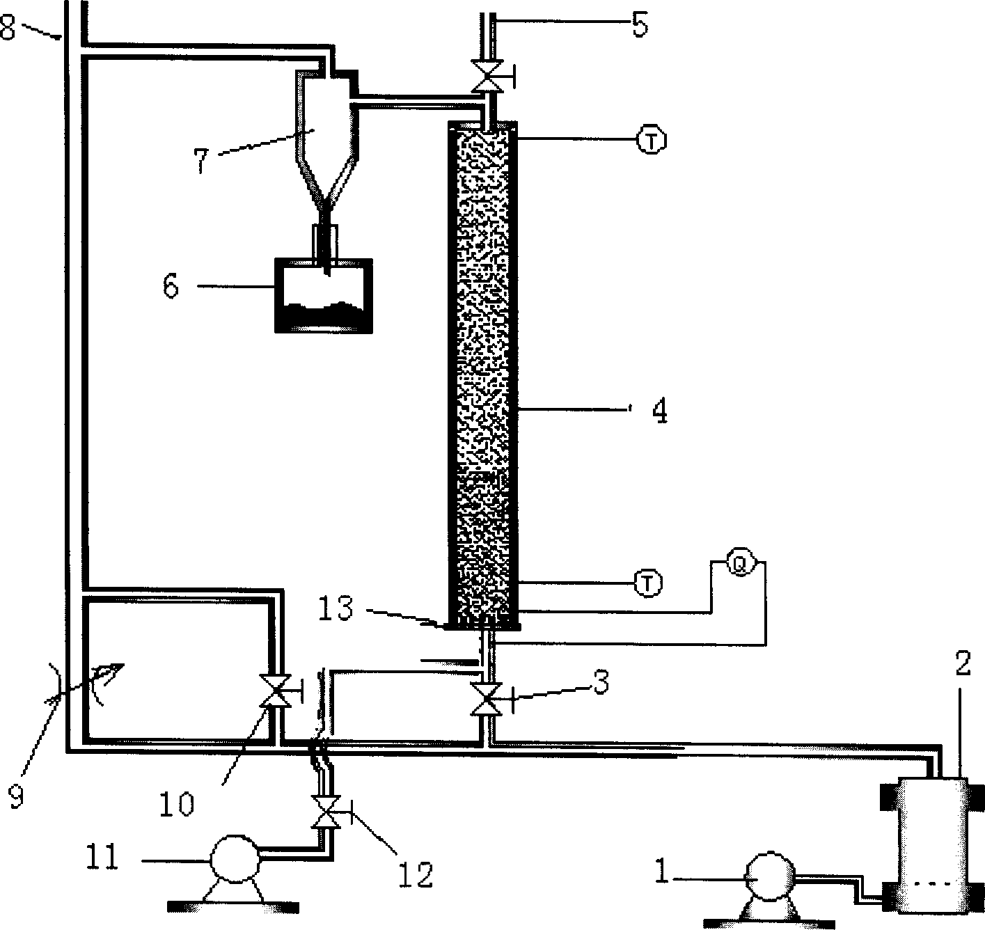
[0014] The structure of the present invention is as shown in the figure: a blower fan 1, a gas generator 2, a separator 7 and a reaction furnace 4 connected through pipelines are provided in sequence. A regulating valve 9 and a switching valve 10 are provided on the pipeline connecting the gasifier 2 and the separator 7 , and a material receiving device 6 is provided at the lower part of the separator 7 . A communicating pipeline is provided between the gas generator 2 and the reaction furnace 4, and a switching valve 3 is provided on the pipeline. The bottom of the reaction furnace 4 communicates with the fan 11 through a pipeline, and a control valve 12 is arranged on the pipeline. The switc...


PUM


Abstract

Structure of the testing device is as following: blower fan, gas generator, separator and reaction furnace are connected to each other through pipe; adjustable valve and switch valve are setup at pipe connected between the gas generator and the separator; material receiver is at lower part of the separator; the gas generator and reaction furnace are connected through pipe with switch valve; being setup at upper, middle, and lower part of the reaction furnace, the test points are in use for thermocouple to measure reduction gas in the furnace, temperature in furnace chamber and temperature of tail gas; through pipe with control valve, the bottom part of the reaction furnace is connected to the blower fan, and test points are in use for measuring flux of coal gas and component. Features are: low energy consumption; the testing device can be added to furnace and demount from furnace quickly, measuring reaction change velocity from weak magnetism to strong magnetism, etc.

Description

technical field [0001] The invention relates to the field of equipment, in particular to a test device for flash magnetization roasting reaction speed of refractory iron oxide ore. Background technique [0002] At present, the main reason why my country's red iron ore has not been fully utilized is that it is difficult to obtain good beneficiation indicators for red iron ore beneficiation. It is the key to further utilize my country's red iron ore resources to achieve a breakthrough in my country's red iron ore beneficiation technology through research on new processes and devices. The roasting magnetic separation method has the advantages of high technical indicators, and is considered to be the most effective method for processing low-grade refractory iron ore. However, the ore particle size of the shaft furnace reduction roasting used in the past is relatively coarse (75-15mm), the magnetization roasting time of the material is long (about 1-2 hours), and the reduction p...

Claims


Application Information

Patent Timeline
Patent Type & Authority Applications(China)
IPC IPC(8): G01N31/00G01N1/28G01N25/22G01N33/24
Inventor 余永富刘根凡梅丰冯志力李华飞
Owner HUAZHONG UNIV OF SCI & TECH
Why Eureka
Try Eureka