Process for producing oxide thin film and production apparatus therefor

A technology of oxide film and manufacturing method, which is applied in semiconductor/solid-state device manufacturing, gaseous chemical plating, coating and other directions, can solve the problems of many defects, worsened ferroelectric properties, and increased leakage current density, etc. Defect improvement, less leakage current, and alignment effect

Active Publication Date: 2006-10-04
ULVAC INC
View PDF0 Cites 4 Cited by
  • Summary
  • Abstract
  • Description
  • Claims
  • Application Information

AI Technical Summary

Problems solved by technology

In this case, if the amount of oxygen mixed (oxygen flow rate ratio) is increased, the leakage current density can be reduced, but since it affects the movement of atoms during crystal growth, the non-crystalline or permanent dielectric layer with a different orientation from the ferroelectricity growth, ferroelectric properties deteriorate
Conversely, if the oxygen flow ratio is reduced, a well-oriented film can be obtained close to epitaxial growth, but the leakage current density increases due to residual organic matter or oxygen defects

Method used


Image

  • Process for producing oxide thin film and production apparatus therefor
  • Process for producing oxide thin film and production apparatus therefor
  • Process for producing oxide thin film and production apparatus therefor

Examples


Embodiment 1

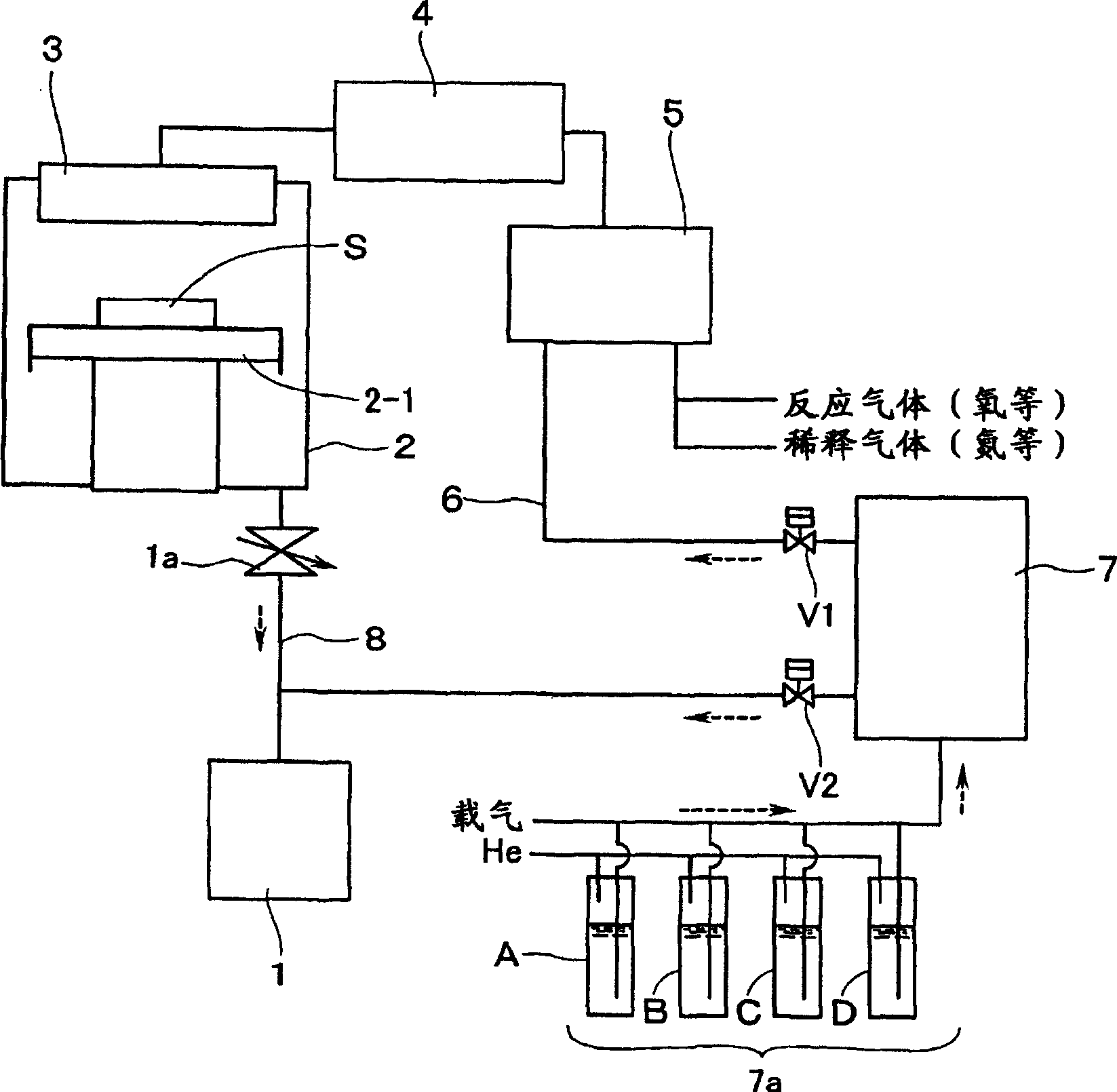
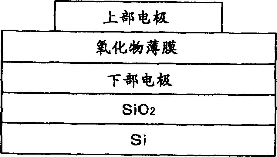
[0078] Add the solid raw material Pb (thd) dissolved in the concentration of 0.3mol / L respectively in the tetrahydrofuran (THF) solvent 2 、Zr(dmhd) 4 、Ti(i-PrO) 2 (thd) 2 Containers A, B, and C of raw materials and THF-filled container D are pressurized with helium and sent to the vaporizer 7 with nitrogen as a carrier gas. Gasification is carried out in the gasifier. The raw material gas obtained by vaporization is sent to the gas mixer 5 through the pipe 6, mixed with oxygen (flow rate 3500 sccm) as the oxidizing gas and nitrogen (300 sccm) as the diluent gas (carrier gas) in the gas mixer 5, and then passed through the gas The activation means 4 sends the mixed gas to the jetting plate 3, passes through the jetting plate, and introduces it onto the substrate S placed in the reaction chamber 2 and heated to 620° C. to deposit and form a PZT thin film.

[0079] In the above process, the pressure of the reaction chamber is adjusted to about 667Pa by the pressure regulating...

Embodiment 2

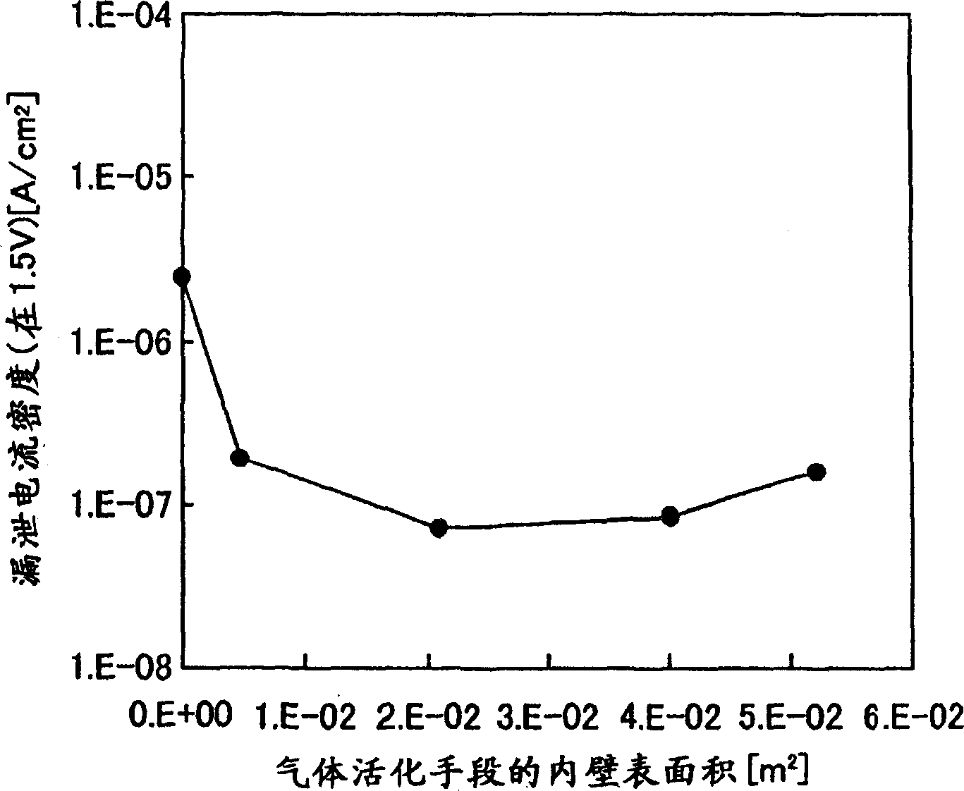
[0084] This example describes the dependence of the inner wall surface of the gas activation means disposed between the gas mixer and the injection plate on the properties of the PZT thin film.

[0085] image 3 Indicates the surface area of ​​the inner wall of the gas activation means (m 2 ) and the leakage current density (A / m 2 ) dependencies. In this case, the ratio of the oxygen gas flowing into the reaction chamber 2 to the total supply gas was 91%. As the substrate, an Ir(111) oriented film was used. Leakage current density when not using gas activation means (internal surface area 0m 2 ) is 2.5E-6A / cm 2 , The surface area of ​​the inner wall is 4.8E-3m 2 It is 2.0E-7, but it decreases when the surface area of ​​the inner wall is increased, and the surface area of ​​the inner wall is 2.1E-2m 2 When showing the minimum value of 7.5E-8A / cm 2 . If the surface area of ​​the inner wall is increased, the leakage current density increases, and the surface area of ​​th...

Embodiment 3

[0091] This example describes the dependence of the ratio of oxygen flow on the properties of PZT thin films.

[0092] Figure 6 It shows the dependence of the oxygen flow rate ratio of the total gas introduction in the mixed gas and the leakage current density when 1.5V is applied to the PZT film. In this case, the oxygen flow ratio is changed from 0.5 to 95%, and the inner wall surface area of ​​the gas activation means is set to 2.1E-2m 2 , the substrate uses Ir (111) orientation film. When the oxygen flow ratio is 1%, the leakage current density is 1E-1, and as the oxygen flow ratio increases, the leakage current density decreases slowly.

[0093] However, if Figure 7 As shown, in the XRD measurement results of the PZT thin film, the (111) orientation strength is significantly reduced when the oxygen flow rate is 80% (b in the figure) compared with the oxygen flow rate of 5% (a in the figure). Figure 7 In the case of Pb / (Zr+Ti)=1.15. Figure 8 Indicates the dependen...


PUM


Abstract

The invention relates to a method and apparatus for manufacturing an oxide thin film. An oxide thin film having good characteristic properties is prepared by reducing an occurrence of an oxygen defect of the resulting oxide thin film and promoting the epitaxial growth of the film. The oxide thin film is prepared by admixing a raw gas, a carrier gas and an oxidation gas and supplying the resulting gas mixture on a heated substrate placed in a reaction chamber from a shower plate through a gas activating means which is maintained, by a heating means, at such a temperature that any liquefaction, deposition and film-formation of a raw material are never caused, to thus make the oxidation gas react with one another and to prepare the oxide thin film on the substrate. In this case, a rate of the oxidation gas flow rate is not less than 60% on the basis of the gas mixture. Furthermore, a flow rate of oxidation gas used for forming an initial layer by nucleation is less than 60%, and a flow rate of oxidation gas used in a subsequent film-forming process for forming a second layer is not less than 60%. Furthermore, in an apparatus for preparing the oxide thin film, a heating means is arranged between a gas-mixing unit and a shower plate.

Description

technical field [0001] The present invention relates to a method for manufacturing an oxide film and a manufacturing device thereof, in particular to a method for manufacturing an oxide film using a chemical vapor growth (CVD) method and a manufacturing device thereof. Background technique [0002] In recent years, due to the demand for high integration of semiconductor devices, the development of mass production technology by the chemical vapor growth method with good stacking fault film properties has been actively carried out. Among them, fabricated by SiO 2 、TiO 2 、Al 2 o 3 、 Ta 2 o 5 , MgO, ZrO 2 , HfO 2 , (Ba,Sr)TiO 2 , SrTiO 3 Etc. dielectric oxides, Pb(Zr,Ti)O 3 、SrBi 2 Ta 2 o 9 、 Bi 4 Ti 3 o 12 In the case of thin films made of ferroelectric oxides such as ferroelectric oxides, if the oxygen deficiency in the film affects good epitaxial growth, the insulation properties of the constant dielectric oxide film and the ferroelectric oxide film will be re...

Claims


Application Information

Patent Timeline
Patent Type & Authority Applications(China)
IPC IPC(8): H01L21/316C23C16/40C23C16/448C23C16/452
CPCC23C16/452H01L21/3165C23C16/4482C23C16/409H01L21/02164H01L21/02183H01L21/02189H01L21/02175H01L21/02178H01L21/02181H01L21/02271H01L21/02186H01L21/02197H01L21/02304C23C16/0272
Inventor 西冈浩梶沼雅彦山田贵一增田健植松正纪邹红罡
Owner ULVAC INC
Why Eureka
Try Eureka