Electrolytic phosphating process

A technology of electrolytic phosphating and process, which is applied in the field of electrolytic phosphating process of phosphate film, can solve problems such as insufficiency, and achieve the effects of lowering temperature, omitting manpower, and reducing size

Inactive Publication Date: 2007-01-10
DENSO CORP
View PDF2 Cites 16 Cited by
  • Summary
  • Abstract
  • Description
  • Claims
  • Application Information

AI Technical Summary

Problems solved by technology

This reference also describes a film coverage of 50%, and this is not sufficient when cathodic electrolytic treatment is carried out for 10 seconds in a treatment solution consisting only of phosphoric acid, nitric acid and zinc carbonate

Method used


Image

  • Electrolytic phosphating process
  • Electrolytic phosphating process
  • Electrolytic phosphating process

Examples


Embodiment 1-6 and comparative example 1-3

[0093] Examples where Fe ions are not included in the treatment bath:

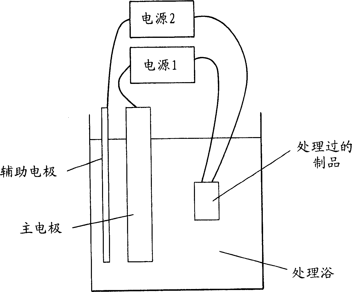
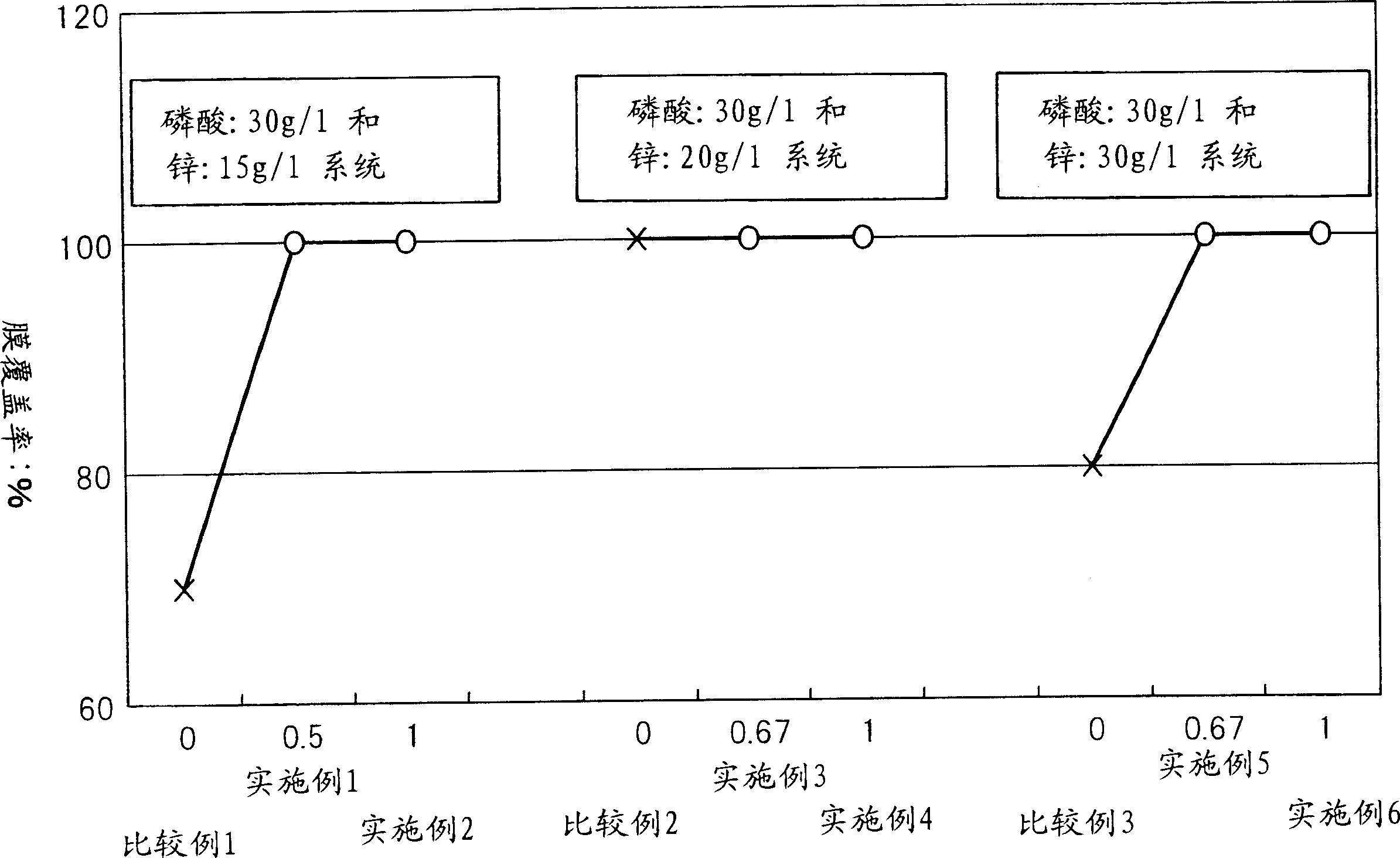
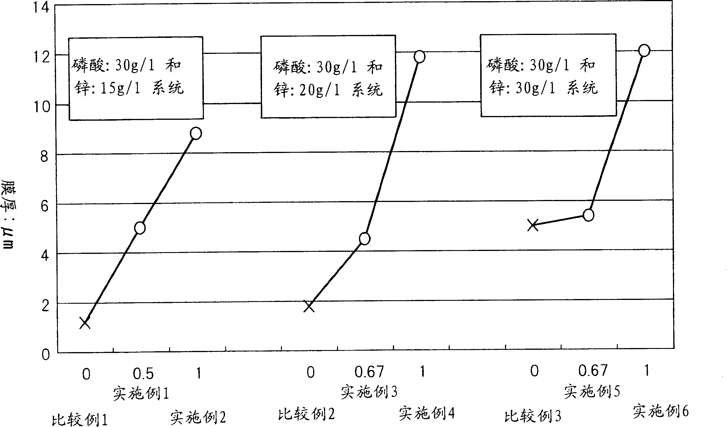
[0094] The test piece used in Examples 1-6 and Comparative Examples 1-3 was a mild steel material (SPCC material: cold-rolled steel plate) having a size of 50 mm×25 mm×1 mm(t). After degreasing, each test piece was immersed in a titanium type colloid solution and subjected to a phosphating process to form a film. The electrolytic phosphating process is performed by anodic treatment (7 seconds) → cathodic treatment (23 seconds). The electrolytic treatment time is 30 seconds, which is shorter than that in the prior art.

[0095] Table 1 lists the conditions and results of the implementation of Examples and Comparative Examples. In other words, Table 1 lists the composition of the phosphating treatment bath, electrolysis conditions, pH value (hydrogen ion concentration) of the treatment bath, ORP (oxidation-reduction potential), temperature, total acidity (from 0.1N caustic soda And titrate 10ml of this tr...

Embodiment 7 and 8 and comparative example 4

[0105] Examples 7 and 8 and Comparative Example 4 are cases of using actual elements (material: SUJ2: high-carbon chromium bearing steel: C: 1%, Cr: 1.45%). This component is a component used in a car brake system and is formed into a gear-like structure by cold forging after lubricating treatment. This forming process is to Figure 5 The shape shown becomes Figure 6 the shape shown. Therefore, used in Examples 7 and 8 and Comparative Example 4 is Figure 5 components shown.

Embodiment 9

[0117] In Example 9 and Comparative Examples 5 and 6, the degree of dissociation of phosphoric acid was adjusted by dissolving iron in phosphoric acid instead of dissolving zinc in phosphoric acid.

[0118] Table 3 gives a summary of the examples. In Example 9 and Comparative Examples 5 and 6, by [H 2 PO 4 - : 100 parts by weight + Zn 2+ : 25 parts by weight] / [H 3 PO 4 ]+[H 2 PO 4 - : 100 parts by weight + Zn 2+ : 25 parts by weight] (mass ratio) [Zn 25% dissolved phosphate ion solution ratio] is all zero. [Zn 25% Dissolved Phosphate Ion Solution Ratio] = 0 Same as in Comparative Examples 1-3. However, it is novel to regulate the degree of dissociation of phosphoric acid by dissolving iron in phosphoric acid.

[0119] Example 10

Example 11

Comparative Example 5

Comparative example 6

Example 9

24

25

26

27

28

treatment bath

composition

Dissociation Index of Phosphoric Acid

[H ...


PUM


Abstract

This invention provides a phosphating process that can form a film suitable for a cold forging foundation within 60 seconds and preferably 30 seconds or less. The process uses a treatment bath that is formed of a phosphate ion solution (H2PO4-+Zn2+), made by dissolving zinc in phosphoric acid, contains phosphoric acid (H3PO4), phosphate ions, zinc ions and nitrate ions, may contain at least one kind of metal ion selected from the group consisting of nickel ions, cobalt ions, copper ions, manganese ions and iron ions, and further contains 0.5 g / l or below of metal ions other than the film forming components. The process involves electrolytic treatment by applying a voltage between a metal as a positive electrode and a treated article as a negative electrode and forms a phosphate film on the surface of the treated article. The phosphate ion solution prepared by dissolving zinc in phosphoric acid (H2PO4-+Zn2+) is a solution obtained by dissolving 8 parts by mass to a maximum dissolution concentration of zinc in 100 parts by mass of phosphoric acid.

Description

technical field [0001] The present invention relates to an electrolytic phosphating process for forming a phosphate film mainly composed of zinc phosphate on the surface of a treated article. More specifically, the present invention relates to a method of forming a film on the surface of a metallic material having electrical conductivity. Background technique [0002] The phosphating process is a treatment technology used for base treatment of coated steel materials, cold forging lubrication treatment, etc. The main phosphating at present is a non-electrolytic treatment, but in order to obtain a more effective phosphating treatment, various electrolytic phosphating processes have been examined. [0003] For example, Japanese Unexamined Patent Publication (Kokai) No. 2000-234200 describes the prior art of electrolytic phosphating, and describes a basic method of using electrodes and a power source when performing electrolytic phosphating. This re...

Claims


Application Information

Patent Timeline
Patent Type & Authority Applications(China)
IPC IPC(8): C25D11/36
CPCC25D9/04
Inventor 松田茂树
Owner DENSO CORP
Why Eureka
Try Eureka