Metal-based carbon fiber composite material and method for producing the same

A composite material and manufacturing method technology, applied in nanotechnology for materials and surface science, thin material processing, nanotechnology for information processing, etc., can solve the problems of reducing the strength and thermal conductivity of composite materials, and achieve Cheap and easy method, light weight effect

Inactive Publication Date: 2007-01-10
岛根县
View PDF6 Cites 20 Cited by
  • Summary
  • Abstract
  • Description
  • Claims
  • Application Information

AI Technical Summary

Problems solved by technology

It is known that carbides such as Al4C3 contact with water or water vapor at room temperature and deteriorate into hydrocarbon gases such as methane and metal hydroxides. There is a gap between the base metal and the matrix metal, and the strength and thermal conductivity of the composite material are greatly reduced

Method used


Image

  • Metal-based carbon fiber composite material and method for producing the same
  • Metal-based carbon fiber composite material and method for producing the same
  • Metal-based carbon fiber composite material and method for producing the same

Examples


Embodiment 1

[0060] 6g of aluminum powder (manufactured by Kishida Chemical Co., Ltd.) with an average particle diameter of 30 μm and 3 g of pitch-based carbon fibers with a fiber length of 20 cm and a diameter of 10 μm (manufactured by Japan Graphite Faiba One, YS) were placed in a rod mill with an inner diameter of 13 mm. -95A), and a glass rod with a diameter of 5 mm x a length of 20 mm. Mixing was carried out by rotating the rod mill along the axis of the rod mill to obtain a metal fiber mixture.

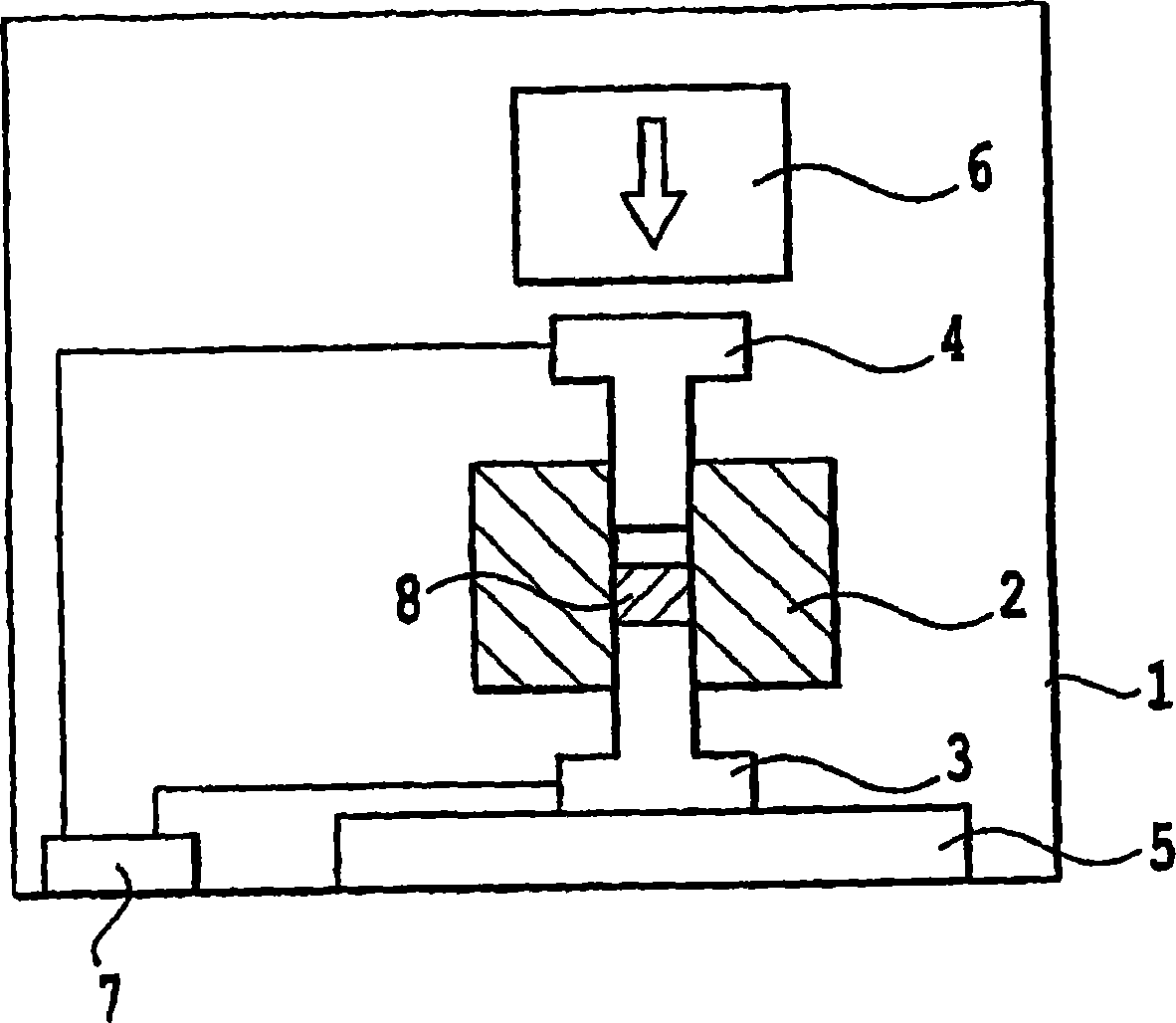
[0061] Next, at figure 1 The device shown is filled with a metal fiber mixture and the pressure inside the device is set at 8Pa. In this example, a mold having through holes of 20×20 cm was used. The mold and the lower punch are fitted together, and the metal fiber mixture is filled in the concave part formed by this, and the carbon fiber is aligned in one direction. Next, an upper punch was placed above the filled metal fiber mixture, and a pressure of 25 MPa was applied by a plunger.

...

Embodiment 2

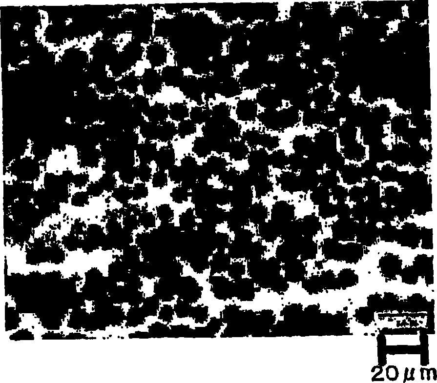
[0065] The procedure of Example 1 was repeated except that the amount of carbon fiber was changed to 4 g and the amount of aluminum powder was changed to 4 g. The resulting metal-matrix carbon fiber composite contains 60% carbon fibers based on the total weight of the composite and has a mass of 1.75 g / cm 3 Density. The ideal density of this material is 2.38g / cm 3 , the relative density is 73%. The thermal conductivity of the obtained composite material was measured, and a value of 300 W / mK was obtained in the direction in which the carbon fibers were arranged.

Embodiment 3

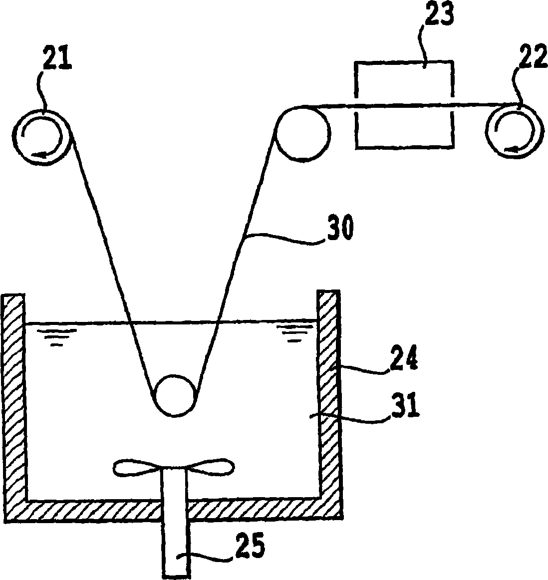
[0067] This embodiment provides the following metal-based carbon fiber composite material: for carbon fibers that can be treated as continuous fibers, a metal fiber mixture is prepared by using a suspension impregnation method using an aluminum powder suspension, and the prepared metal fiber mixture is sintered by a pulse energization sintering method. Sintering to obtain metal matrix carbon fiber composites.

[0068] As the carbon fibers, pitch-based carbon fibers having a diameter of 10 μm having a thermal conductivity of 1000 W / mK were used, and a bundle of 6000 of these fibers was wound on the pay-off reel 2 . As the aluminum powder, a flaky powder having a thickness of 1 μm or less and an average representative length in the planar direction of 30 μm was used. In ethanol containing 2% by weight (based on the weight of ethanol) of a dispersion binder (Pluronic (registered trademark) F68), aluminum powder was mixed to form a metal powder suspension. The content of aluminum...


PUM

PropertyMeasurementUnit
densityaaaaaaaaaa
densityaaaaaaaaaa
densityaaaaaaaaaa

Abstract

A method is provided for producing a metal-based carbon fiber composite material lightweight, high in the thermal conductivity and also capable of controlling the direction of heat flow, while inhibiting metal carbide formation. The method for producing the metal-based carbon fiber composite material comprises the steps of: obtaining a metal fiber mixture by physically mixing carbon fiber with metal powder; filling the metal fiber mixture into a jig, while the metal fiber mixture is aligned; and setting the jig in an air, vacuum or inert gas atmosphere and directly supplying pulse electric current to the metal fiber mixture, with applying a pressure, to effect sintering by the heat generated therefrom. Here, the composite material contains 10 to 80 % by weight of carbon fiber based on a total weight of the composite material and is sintered at 70% or more of ideal density.

Description

technical field [0001] The present invention relates to metal matrix carbon fiber composite materials. More specifically, it relates to a metal-matrix carbon fiber composite material with high thermal conductivity suitable for heat dissipation of devices operating from normal temperature to hundreds of degrees Celsius, and a method for manufacturing metal-matrix carbon fiber composite materials by pulse energization sintering. Background technique [0002] Conventionally, metals with high thermal conductivity such as aluminum or copper or alloys thereof are used as heat dissipation components (base plates, heat sinks, heat spreaders, etc.) of electronic devices using semiconductors or power modules. However, as the performance of these devices increases, the heat generation tends to increase significantly. In addition, along with the reduction in size and weight of these devices, reduction in size and weight of heat dissipation components is required. [0003] In view of t...

Claims


Application Information

Patent Timeline
Patent Type & Authority Applications(China)
IPC IPC(8): C22C49/14C22C47/14B22F3/14H01L23/373
CPCB22F2003/1051C22C2026/002C22C47/14B82Y10/00C22C49/14B22F2999/00B22F2998/00C22C47/025B82Y30/00H01L2924/0002Y10T428/249924C22C26/00B22F3/14B22F3/105B22F2201/10B22F2201/20H01L2924/00H01L23/373
Inventor 佐藤公纪尾添伸明小川仁一上野敏之小松原聪
Owner 岛根县
Why Eureka
Try Eureka