Extraction of copper from waste etching liquid in chloride system circuit board

An extraction method and a technology of waste etching solution, which are applied in the field of electrodeposition and extraction of copper in the waste etching solution of the chloride system circuit board, can solve the problems of less precipitation, inability to treat the waste etching solution, and reduce the efficiency of direct current Faraday, etc., to achieve Effect of High DC Current Efficiency

Inactive Publication Date: 2007-01-17
李海涛 +2
View PDF2 Cites 8 Cited by
  • Summary
  • Abstract
  • Description
  • Claims
  • Application Information

AI Technical Summary

Problems solved by technology

[0002] The non-renewable waste etching solution of the chloride system circuit board contains about 100g to 120g of copper per liter. Only Guangdong Province produces about 5,000 tons of copper in this type of waste etching solution every month. The copper is recycled for recycling Utilization has very significant economic value, and in the existing method for extracting copper in the waste etching solution of this chloride system circuit board, it is mainly in the electrolyzer that is separated into cathode area and anode area by diaphragm material, The anode terminal and the cathode terminal are respectively connected to the positive terminal and the negative terminal of the DC output power supply. After the circuit is connected, the waste etching solution in the electrolytic cell is electrolyzed. At the initial stage of electrification, the amount of copper deposited on the cathode is very small. After a long period of time, after the temperature of the waste etching solution is significantly increased due to the Joule heating effect, the copper precipitation speed at the cathode is accelerated until the copper in the waste etching solution is almost completely precipitated. At this time, if it is assumed that the copper ions in the waste etching solution are all The divalent valence state exists, and its Faraday DC efficiency is below 70%. At the same time, the corresponding chlorine gas is precipitated on the anode. According to theoretical calculations, every 100kg of copper electrodeposited, 111.6kg of copper is deposited on the anode. Chlorine gas has a standard volume of 35.26m 3 , to properly handle such a large amount of chlorine without causing secondary pollution to the environment is a very costly investment, and there is also the problem of waste liquid treatment
To address these problems, Chinese patent application ZL97121340.2 discloses a regenerated CuCl 2 The device and me

Method used


Image

  • Extraction of copper from waste etching liquid in chloride system circuit board

Examples


Embodiment 1

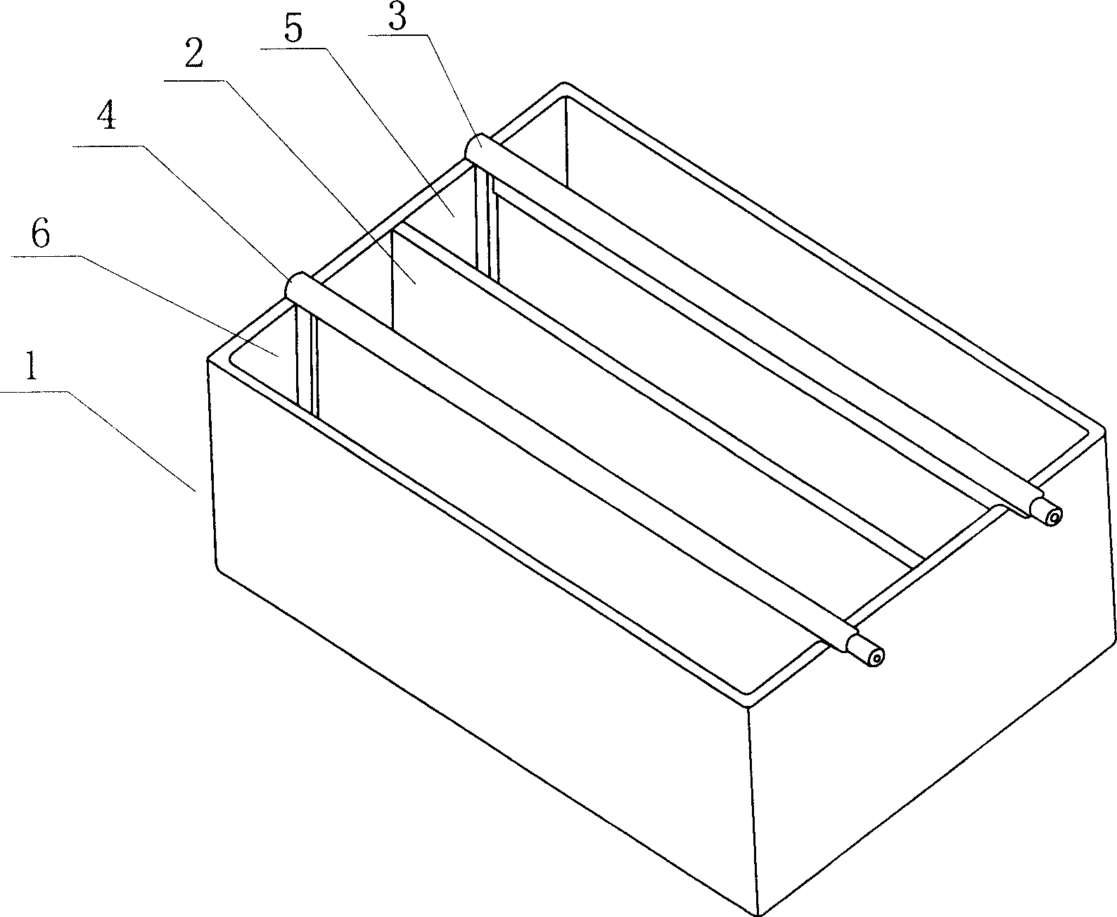
[0017] Example 1: In such as figure 1 In the cathode region 6 of the electrolytic cell shown, waste etching solution for circuit boards in a chloride system containing 105.29 g / L of copper is added, and a chloride conductive medium is added in the anode region 5 . And after adding the mixture of zinc and iron, the anode 3 and cathode 4 in the electrolytic cell are connected to the positive and negative terminals of the DC power supply to form a loop, and then the power is turned on for copper electrodeposition. The ambient temperature is 28°C, and the cathode 4 The current density is 700A / m 2 to 800A / m 2 , the amount of electricity fed into the electrodeposition operation is 105.6Ah, and the amount of deposited copper obtained on the cathode 4 is 124g. Calculated by divalent copper, the theoretical amount of copper deposited per Ah is 1.185g, and the DC current efficiency calculated from this is 99.1 %, no chlorine gas is released on the anode 3, and new compounds are genera...

Embodiment 2

[0018] Embodiment 2: in the electrolyzer identical with embodiment 1, add the compound identical with example 1 in the anode area 5, add new chloride system circuit version waste etching solution in the cathode area 6, electrode and DC power supply are connected into After the electrolysis circuit, turn on the electrolysis power supply, and operate the electrodeposition copper until all the copper in the etching solution is precipitated on the cathode 4, and the etching solution mainly presents a clear color, and the accumulated electrolytic power is 334.4Ah, and the cathode area 6 is obtained 384g of deposited copper is calculated to have a Faraday DC current efficiency of 96.9%.

Embodiment 3

[0019] Embodiment 3: by 4 such as figure 1 The shown monomer electrolyzers are connected in series to form a series of electrolyzers. In the cathode area 6 of each monomer electrolyzer, the waste etching solution of the circuit board of the chloride system is added. Add 170L of waste etching solution. Add potassium and sodium chloride solution conductive media in each anode area 5, the concentration of chloride is 200g / L to 220g / L, and add zinc and iron compounds in each anode area 5, connect the anode 3 of the electrolytic cell in series The cathode 4 is connected to the positive terminal and the negative terminal of the DC electrolysis power supply respectively, and the power is turned on for copper electrodeposition operation. The current density of the cathode 4 is about 900A / m 2 , Electrodeposition is carried out until the waste etching solution is clear and transparent, the cumulative total electricity input is 16372Ah, and 18.74Kg of copper products are obtained, and t...


PUM


Abstract

The extraction of copper from waste etching solution of circuit boards in chloride system includes: a electrolysis device containing a electrolytic vessel divided into cathode region and anode region by diafragm material, addition of waste etching solution into the cathode region, addition of chloride salts and elementary substance or compound accessory ingredient which reacts with chlorine as conducting medium, deposition of copper on the cathode and reaction of accessory ingredient with chlorine to form stable chloride in the anode region. Because the individual electrolytic vessel is divided into cathode region and anode region by slightly permeable diafragm, the electrodeposition of copper will progress equably in a large range of cathode current density, corresponding reactions of chlorine from electrolysis with added Mg, Al, Zn, Fe etc. will also occurs in the anode region avoiding the emission of chlorine above the anode.

Description

technical field [0001] The invention relates to a method for extracting copper, in particular to a method for extracting copper by electrodeposition from waste etching solution of circuit boards in a chloride system. Background technique [0002] The non-renewable waste etching solution of the chloride system circuit board contains about 100g to 120g of copper per liter. Only Guangdong Province produces about 5,000 tons of copper in this type of waste etching solution every month. The copper is recycled for recycling Utilization has very significant economic value, and in the existing method for extracting copper in the waste etching solution of this chloride system circuit board, it is mainly in the electrolyzer that is separated into cathode area and anode area by diaphragm material, The anode terminal and the cathode terminal are respectively connected to the positive terminal and the negative terminal of the DC output power supply. After the circuit is connected, the was...

Claims


Application Information

Patent Timeline
IPC IPC(8): C25C1/12C23F1/46
CPCY02P10/20
Inventor 李海涛叶志炜王栋
Owner 李海涛
Why Eureka
Try Eureka