Heat transfer tube for LNG vaporizer, its production method, and LNG vaporizer using such heat transfer tubes

A heat transfer tube and vaporizer technology, applied in the field of LNG vaporizers, can solve problems such as corrosion

Inactive Publication Date: 2007-03-21
KOBE STEEL LTD
View PDF2 Cites 21 Cited by
  • Summary
  • Abstract
  • Description
  • Claims
  • Application Information

AI Technical Summary

Problems solved by technology

However, in the LNG vaporizer, the seawater flowing out from the edge of the tank 8 directly contacts the surface of the heat transfer tub

Method used


Image

  • Heat transfer tube for LNG vaporizer, its production method, and LNG vaporizer using such heat transfer tubes

Examples


Embodiment 1

[0048] 【0037】

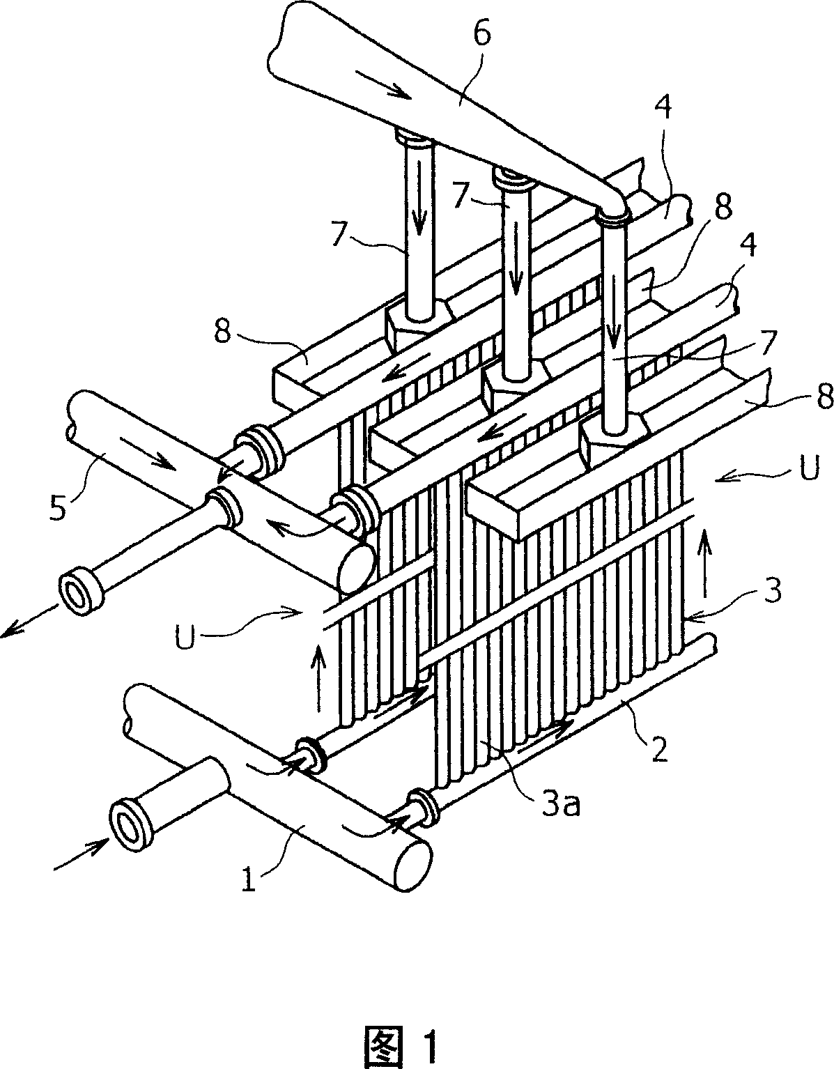
[0049] In order to simulate the environment near the panel 3 and the lower header 2 of an LNG vaporizer (ORV) (see Figure 1), a pure aluminum disc with a diameter of 16 mm and a thickness of 4 mm was prepared, defined by a straight line passing through the center of the disc. On one surface of the disk, a coating having the composition shown in Table 1 was thermally sprayed to have a thickness of 300 micrometers. Test specimens were obtained after thermal spraying without further treatment. The Peltier element was brought into close contact with the rear surface of the sample on the side not subjected to thermal spraying, thereby cooling the rear surface of the sample to 20° C. below the freezing point. The surface of the side on which the thermal spray coating was formed at 20° C. below the freezing point was exposed to commercially available artificial seawater (Marine Art Hi, produced by Tomita Pharmaceutical Co., Ltd.) at 30° C. for 20 hours, and The degr...

Embodiment 2

[0053] One side of a 200 mm x 200 mm aluminum alloy (A5083) plate having a thickness of 5 mm was machined to have various degrees of surface roughness, and the plate was used as an aluminum substrate. The centerline average roughness Ra75 of the aluminum substrate was evaluated using a surface roughness meter immediately after machining. For each group of test conditions, prepare 10 (n=10) aluminum substrates that are machined with the same target surface roughness, and the average value of Ra 75 of these 10 aluminum substrates is used as the The roughness (Ra 75) of the boundary between coats is shown in Table 2. In order to achieve satisfactory adhesion to the aluminum substrate, a 300 μm thick Al- 5% by mass Mg coating. On a partially machined aluminum substrate, an Al-90%Mg coating with a thickness of 300 μm was formed by flame spraying using a wire of Al-90% by mass Mg. The test specimens were obtained after thermal spraying without further treatment. The composition ...

Embodiment 3

[0059] A 200 mm×200 mm aluminum alloy (A5083) plate having a thickness of 5 mm was used as the aluminum base material. An Al-5 mass% Mg alloy was thermally sprayed on one side of this aluminum substrate to form an Al-5 mass% Mg alloy coating. After the thermal spray coating was formed, different post-treatments were performed on the aluminum substrates, and samples 1 to 7 as shown in Table 3 were prepared. Eleven samples were prepared for each post-treatment type.

[0060] make up

No

thermal spray coating

layer thickness

(microns)

after thermal spraying

Machining

after thermal spraying

reason

Pore ​​surface

Product (%)

Blister Peel

area of ​​hundreds

Ratio (%)

note

1

300

No

not dealt with

17.1

44.2

comparative example

2

300

No

inject sealant

18.2

20.4

comparative example

...


PUM

PropertyMeasurementUnit
Thicknessaaaaaaaaaa
Diameteraaaaaaaaaa
Thicknessaaaaaaaaaa

Abstract

A heat transfer tube for an LNG vaporizer in which damage in the surface of the Al alloy substrate by corrosion is effectively prevented even when it is used in the lower portion of the panel or in the lower header where the surface is vigorously cooled and formation of the oxide coating is less likely to take place. This heat transfer tube is used in an LNG vaporizer equipped with an Al alloy panel unit including a panel composed of a plurality of heat transfer tubes arranged in a row in the form of a curtain, and a lower header and an upper header respectively connected to the panel at its lower end portion and its upper end port ion; wherein the LNG is vaporized by heat exchange between seawater flowing down along the surface of the panel from the upper end portion of the panel unit and the LNG flowing through theheattransfertubes. In this LNG vaporizer, the outer surface of the heat transfer tube at least in the lower end portion of the panel and the outer surface of the lower head are subjected to surface roughening by blasting, and then, a coating of an Al-Mg alloy containing Mg at a content in the range of 1 to 80% by mass, and having a thickness of 100 to 1000 m was formed by thermal spraying to realize protection by sacrificial corrosion. Formation as the corrosion protective of an A1 alloy coating containing Zn and/or Mn at a content in the range of 0.3 to 3.0% by mass with the proviso that the content of (Zn + Mn) is in the range of 0.3 to 3.0% by mass and containing Mg at a content in the range of 0. 3 to 5% by mass is also effective.

Description

technical field [0001] The present invention relates to a heat transfer tube for an LNG (liquefied natural gas) vaporizer having excellent corrosion resistance and an LNG vaporizer manufactured by using the heat transfer tube. Background technique [0002] Liquefied natural gas (hereinafter referred to as LNG) is generally transported and stored as a liquid formed at low temperature and high pressure and vaporized before use. For this vaporization, an open rack vaporizer (hereinafter referred to as ORV) is generally used because the ORV can vaporize a large amount of LNG. Fig. 1 shows a typical ORV, and as shown in the figure, the ORV is a heat exchanger in which LNG is heated to be vaporized by heat exchange with seawater (for example, see Patent Document 1) . Seawater enters from a seawater header 6 and flows through nozzles 7 to be stored in tanks 8 . The seawater flowing from the edge of the tank 8 flows down the outer surface of the panel 3 c...

Claims


Application Information

Patent Timeline
IPC IPC(8): F28F19/06F28D1/053
CPCF28F19/06
Inventor 漆原亘加藤淳安永龙哉
Owner KOBE STEEL LTD
Why Eureka
Try Eureka