Alignment system for photoetching device and stage jointing grating system

An alignment system and lithography technology, applied in microlithography exposure equipment, photolithography exposure devices, optics, etc., can solve the problems of increasing the complexity of the drive system and low alignment accuracy, and achieve the suppression of interference and destructive effects The influence of the structure, good structural stability, and the effect of improving the strength of the alignment signal

Active Publication Date: 2007-03-28
SHANGHAI MICRO ELECTRONICS EQUIP (GRP) CO LTD
View PDF1 Cites 51 Cited by
  • Summary
  • Abstract
  • Description
  • Claims
  • Application Information

AI Technical Summary

Problems solved by technology

Although this technology uses two sets of alignment marks, coarse and fine, to improve the alignment capture range, on the one hand, the two-stage drive increases the complexity of the drive system and also increases the instabilit

Method used


Image

  • Alignment system for photoetching device and stage jointing grating system
  • Alignment system for photoetching device and stage jointing grating system
  • Alignment system for photoetching device and stage jointing grating system

Examples


Embodiment Construction

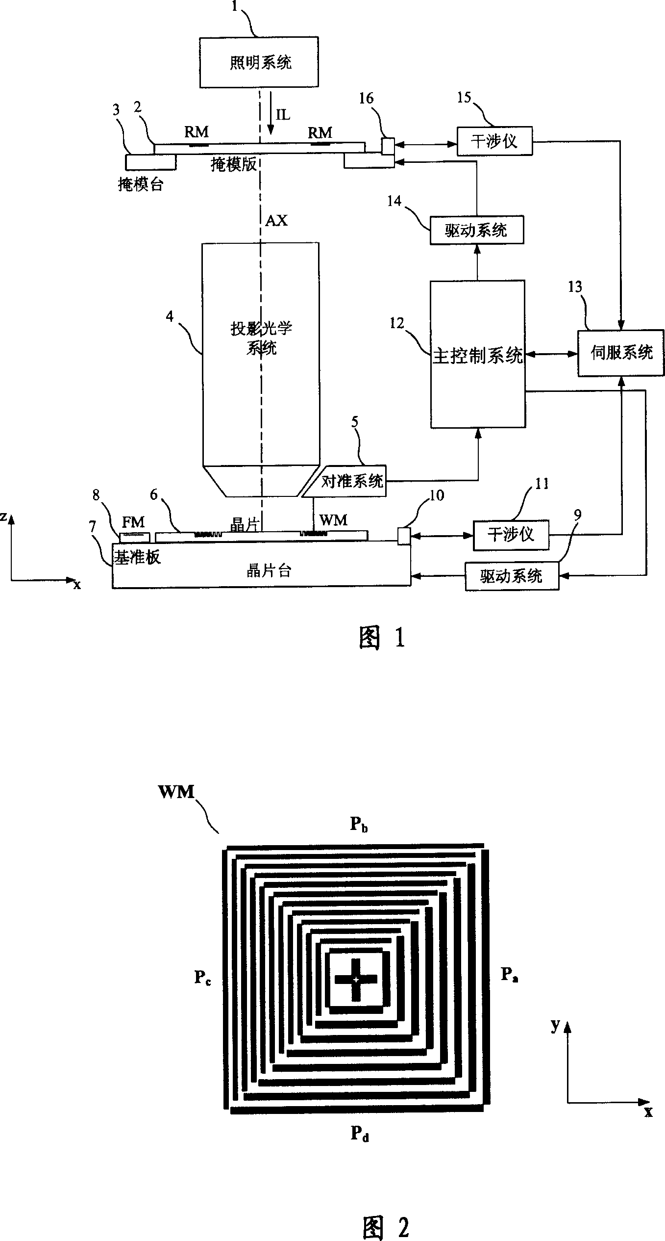
[0065] Fig. 1 is a schematic structural view of a lithography apparatus according to a specific embodiment of the present invention, as can be seen from Fig. 1, its composition includes: an illumination system 1 for providing an exposure beam; a mask holder and a mask table 3 for supporting a reticle 2, There is a mask pattern on the reticle 2 and an alignment mark RM with a periodic structure; a projection optical system 4 for projecting the mask pattern on the reticle 2 onto a wafer 6; a wafer holder and a wafer for supporting the wafer 6 Stage 7, on wafer stage 7 there is fiducial plate 8 engraved with fiducial mark FM, on wafer 6 there is alignment mark WM of periodic optical structure; Alignment system 5 of the system; mirrors 10, 16 and laser interferometers 11, 15 for position measurement of mask stage 3 and wafer stage 7, and displacement of mask stage 3 and wafer stage 7 controlled by main control system 12 Servo system 13 and drive system 9,14.

[0066] The illumina...


PUM


Abstract

This invention discloses a kind of optical-mechanical system which is used in photoetching machine and on it, and its matching system includes light source module supplying light. Transmitting light beam, vertical illumination crystal plate cyclicity optical structure alignment mark lighting unit. To collect alignment mark the multilevel diffracted ray by using microobjective. To realize the multi-wavelength separated by using the polychromatic light separated system. To correspond the positive and negative diffraction spectrum of the alignment mark with the imaging units by using level-bonded grating system. To measure the changing of the light intensive and the phase for the several wave-length and the levels spectrum spot by using the differential Mohr-message detection method, so we can got the detective unit of the alignment mark message. The level-bonded grating system includes the grating, the reflecting mirror and the prism, to overlay the +1-+n level and the -1--n level of the alignment mark message mark with the positive and negative diffraction spot. It can supply highly alignment accuracy and stability.

Description

technical field [0001] The invention relates to a lithographic device in the field of integrated circuit IC or other micro device manufacturing, and relates to an alignment system for the lithographic device and a level-combined grating system thereof. Background technique [0002] Lithography equipment is mainly used in the manufacture of integrated circuits IC or other micro-devices. With a photolithographic apparatus, multilayer masks with different mask patterns are sequentially imaged in precise alignment on a photoresist-coated wafer, such as a semiconductor wafer or an LCD panel. [0003] IC devices manufactured by photolithography technology require multiple exposures to form multilayer circuits in the wafer. For this reason, an alignment system is required in the photolithography device to achieve precise alignment between the mask and the wafer. When the feature size "CD" is required to be smaller, the requirements for overlay accuracy "Overlay" and the resulting ...

Claims


Application Information

Patent Timeline
IPC IPC(8): G03F9/00G03F7/20H01L21/027G02B27/44
Inventor 徐荣伟李铁军
Owner SHANGHAI MICRO ELECTRONICS EQUIP (GRP) CO LTD
Why Eureka
Try Eureka