Method of manufacturing chemical mechanical polishing pad and polishing pad
A chemical machinery, polishing pad technology, applied in surface polishing machine tools, manufacturing tools, grinding/polishing equipment, etc., can solve problems such as unsatisfactory polishing rate and polishing surface state
- Summary
- Abstract
- Description
- Claims
- Application Information
AI Technical Summary
Problems solved by technology
Method used
Image
Examples
Embodiment 1
[0151] (1) Manufacture of chemical mechanical polishing pads
[0152] 80 parts by volume (equal to 72 parts by weight) of 1,2-polybutadiene (manufactured by JSR Corporation under the trademark JSR RB830) and 20 parts by volume (equal to 28 parts by weight) of β-cyclodextrin (manufactured by Bio Research Corporation of Yokohama, under the trademark Dexy Pearl β-100, with an average particle diameter of 20 µm) were stirred together. Add 1.0 parts by volume of Percumyl D40 (trademark, manufactured by NOF Corporation, containing 40% by mass of dicumyl peroxide) (equal to 0.44 parts by weight of pure dicumyl peroxide) as dicumyl peroxide and in Stirring together with the above stirring product at 120° C. to obtain pellets of the composition for forming a chemical mechanical polishing pad. The pellets were fed into a mold and heated at 170° C. for 18 minutes to crosslink them, so that a disk-shaped molded product (cushion) having a diameter of 600 mm and a thickness of 2.5 mm was o...
Embodiment 2
[0163]28.2 parts by weight of polytetramethylene glycol (manufactured by Mitsubishi Chemical Co., Ltd., trademarked as PTMG650) and 21.7 parts by weight of 4,4'-diphenylmethane diisocyanate (made by Sumika BayerUrethane Co., . Ltd., the trademark is Sumidule 44S) into the reactor and stirred at 90 ° C for 3 hours to react, and then cooled to obtain a prepolymer having isocyanate groups at both ends, wherein the polytetramethylene glycol It has two hydroxyl groups at both ends of the molecule and has a number average molecular weight of 650.
[0164] 14.5 parts by weight of β-cyclodextrin (manufactured by Bio Research Corporation of Yokohama, under the trademark Dexy Pearl β-100, with an average particle diameter of 20 μm) was dispersed as water-soluble particles into 21.6 parts by weight of polypropylene glycol (made by manufactured by NOF Corporation under the trade name Uniol TG300, an addition reaction product of glycerin and propylene oxide) and 6.9 parts by weight of PTMG...
Embodiment 3
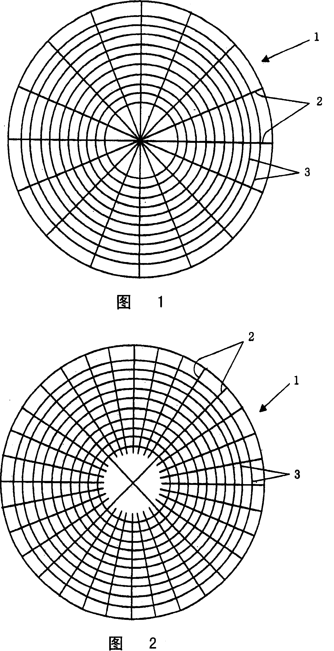
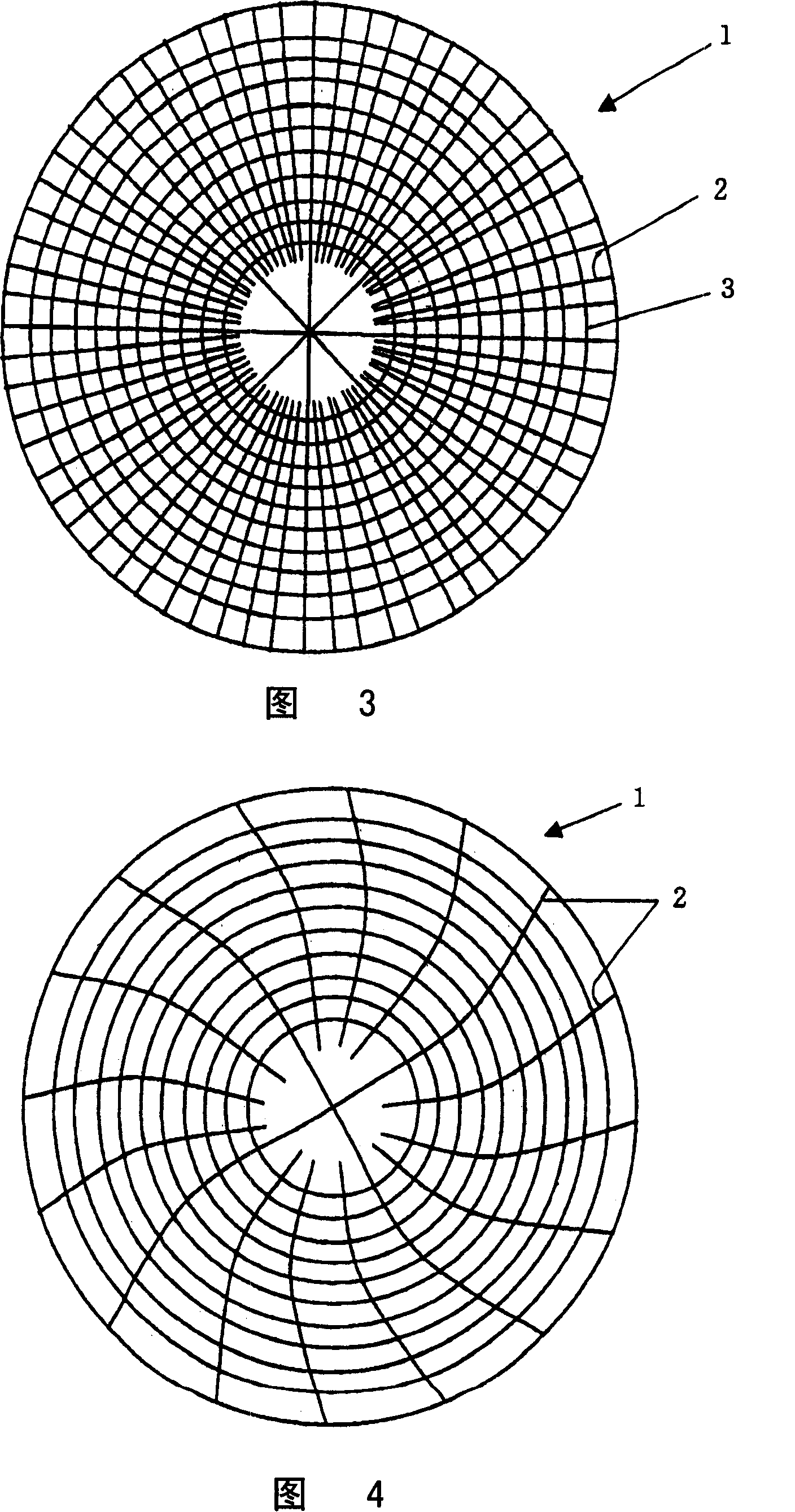
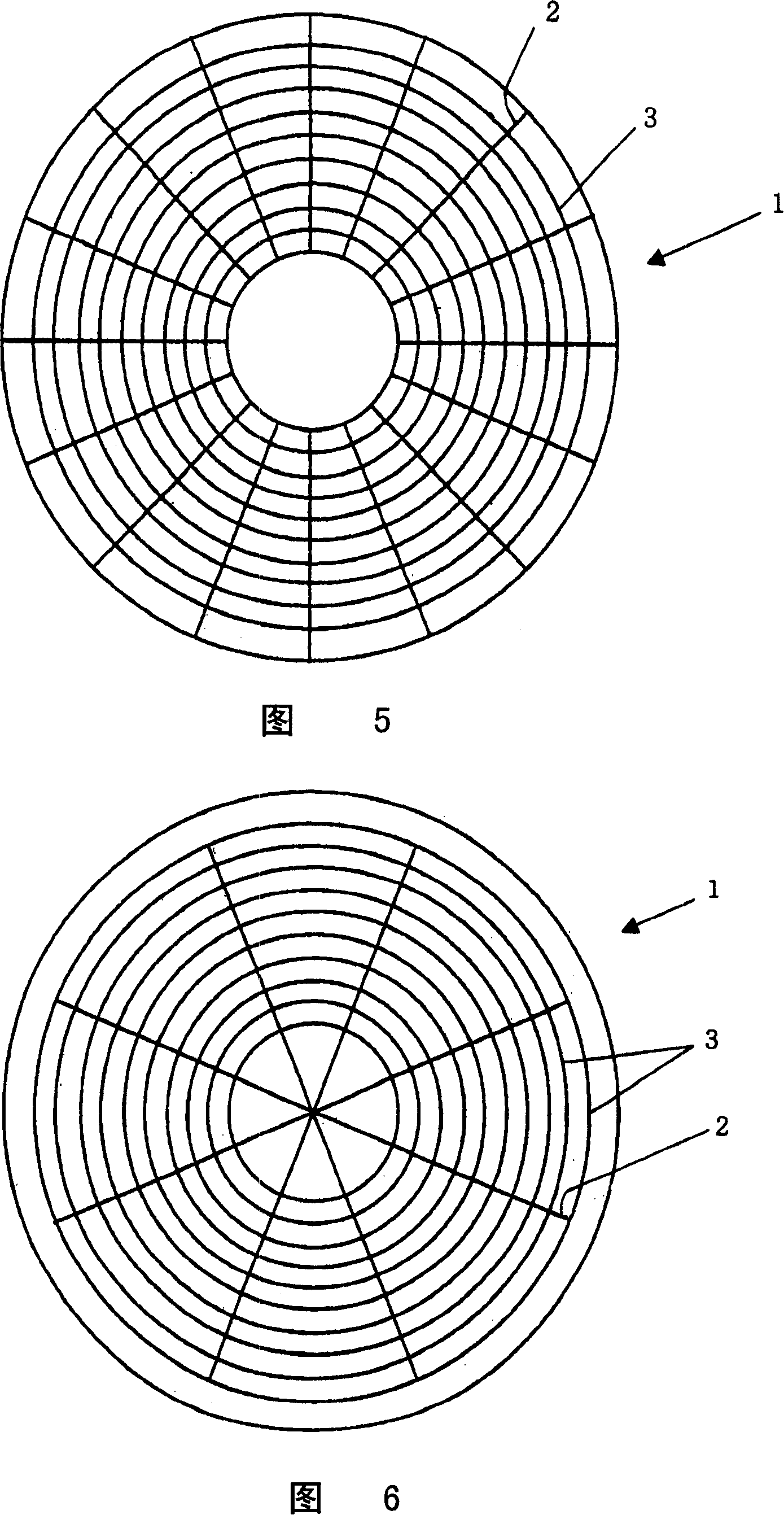
[0170] After forming the first set of grooves in the pad of Example 1, four linear grooves (with a width of 1.0 mm) extending from the center of the pad to the peripheral end were formed by a cutting machine equipped with a drive unit capable of indexing angles and positioning and a depth of 1.0 mm) as a second set of grooves, these grooves contact each other at the center of the pad polishing surface and the angle between adjacent linear grooves is 90°. four slots with Figure 9 The second set of four grooves that touch each other at the center correspond. Four slots are formed using one milling cutter. In addition, 28 pairs of linear grooves (with a pitch of 2 mm between grooves) extending from a point 25 mm from the center of the pad to the peripheral end of the pad were formed by the same cutting machine as above, and the angle between adjacent linear grooves is 11.25°. 28 pairs of slots with Figure 9 The 28 pairs of slots shown correspond. These pairs of grooves wer...
PUM
| Property | Measurement | Unit |
|---|---|---|
| diameter | aaaaa | aaaaa |
| thickness | aaaaa | aaaaa |
| width | aaaaa | aaaaa |
Abstract
Description
Claims
Application Information
 - R&D
- Intellectual Property
- Life Sciences
- Materials
- Tech Scout
- Unparalleled Data Quality
- Higher Quality Content
- 60% Fewer Hallucinations
Browse by: Latest US Patents, China's latest patents, Technical Efficacy Thesaurus, Application Domain, Technology Topic, Popular Technical Reports.
© 2025 PatSnap. All rights reserved.Legal|Privacy policy|Modern Slavery Act Transparency Statement|Sitemap|About US| Contact US: help@patsnap.com


