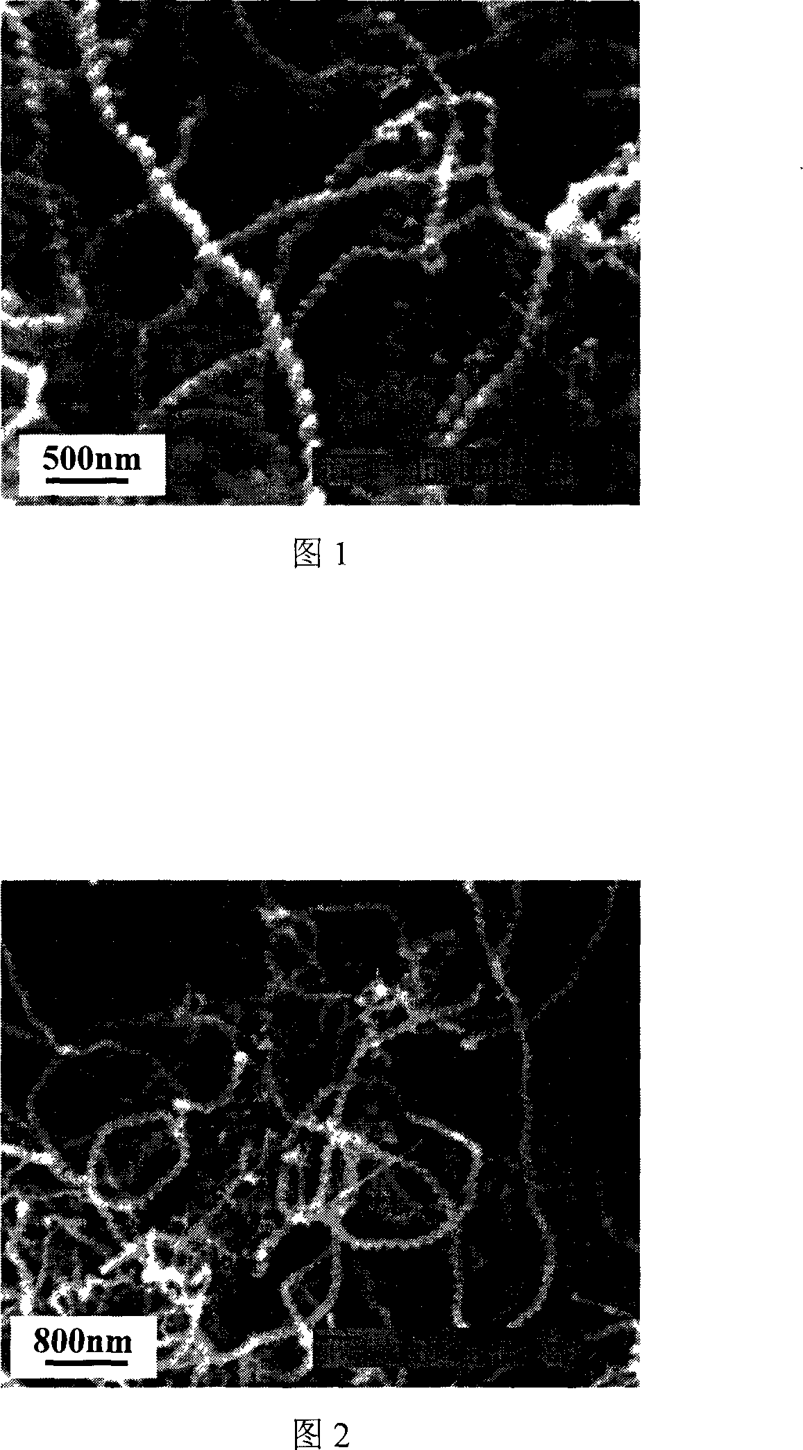
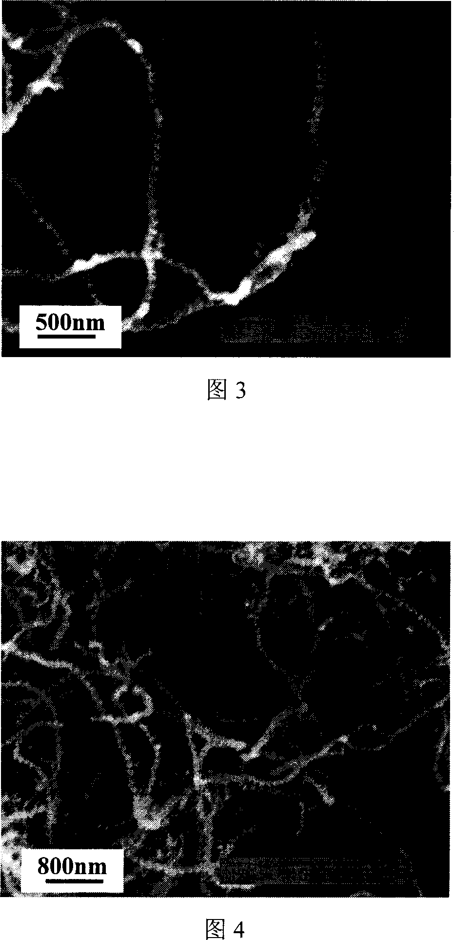
Method for preparing spiral nano carbon fiber
A carbon nanofiber and helical technology, which is applied in the field of preparing helical carbon nanofibers, can solve the problems of difficult preparation of small-diameter catalysts, difficult to clean up, complicated preparation process, etc., and is conducive to mass production, the method is simple and easy to operate, and the wide The effect of the application foreground
- Summary
- Abstract
- Description
- Claims
- Application Information
AI Technical Summary
Problems solved by technology
Method used
Image
Examples
Embodiment 1
[0015] Before the reaction, the nickel plate catalyst with a thickness of 1mm and a length and width of 150mm and 30mm was subjected to surface treatment, and the surface of the nickel plate was subjected to high-speed sandblasting for 30 minutes, then soaked in dilute hydrochloric acid for 5 hours, dried and placed in a tube furnace In the constant temperature zone, the nickel plate catalyst is placed horizontally on the graphite plate; the reaction system is evacuated, replaced with nitrogen three times, and nitrogen is introduced. The flow rate of nitrogen is 200ml / min. Simultaneously add PCl with hydrogen as carrier gas 3 Cocatalyst, PCl 3 The flow rate of cocatalyst is 0.03ml / min, the ratio of diluent gas nitrogen and acetylene flow is 2.5:1 (wherein: acetylene is 40ml / min, nitrogen is 100ml / min), the ratio of hydrogen and acetylene flow is 3:1 (wherein : Acetylene is 40ml / min, hydrogen is 120ml / min), and the reaction constant temperature time is 35min, carries out catal...
Embodiment 2
[0017] Before the reaction, the nickel plate catalyst with a thickness of 1.5mm and a length and width of 150mm and 30mm was subjected to surface treatment, and the surface of the nickel plate was subjected to high-speed sandblasting for 30 minutes, then soaked in dilute sulfuric acid for 8 hours, dried and placed in a tubular In the constant temperature zone of the furnace, the nickel plate catalyst is vertically placed on a horizontal graphite plate; the reaction system is evacuated, replaced with argon for three times, and fed with argon. The flow rate of argon is 200ml / min, and the temperature is raised to At 670°C, add PCl with hydrogen as the carrier gas while feeding acetylene 3 Cocatalyst, PCl 3 The flow rate of co-catalyst is 0.04ml / min, the ratio of diluent gas argon to acetylene flow is 2:1 (among them: acetylene is 50ml / min, argon is 100ml / min), the ratio of hydrogen to acetylene flow is 3.5:1 (Among them: acetylene is 50ml / min, hydrogen is 175ml / min), the reactio...
Embodiment 3
[0019] Before the reaction, the nickel plate catalyst with a thickness of 0.5mm and a length and width of 150mm and 30mm was subjected to surface treatment, and the surface of the nickel plate was subjected to high-speed sandblasting for 30 minutes, then soaked in dilute hydrochloric acid for 5 hours, dried and placed in a tubular In the constant temperature zone of the furnace, the nickel plate catalyst is placed horizontally on the graphite plate; the reaction system is evacuated, replaced with nitrogen three times, and nitrogen is introduced. The flow rate of nitrogen is 200ml / min, and the temperature is raised to 680°C under nitrogen atmosphere, and acetylene is introduced. While adding PCl with hydrogen as carrier gas 3 Cocatalyst, PCl 3 The flow rate of cocatalyst is 0.05ml / min, the ratio of diluent gas nitrogen and acetylene flow is 3:1 (wherein: acetylene is 45ml / min, nitrogen is 135ml / min), the ratio of hydrogen and acetylene flow is 4:1 (wherein : acetylene is 45ml / ...
PUM
| Property | Measurement | Unit |
|---|---|---|
| thickness | aaaaa | aaaaa |
Abstract
Description
Claims
Application Information
 - R&D
- Intellectual Property
- Life Sciences
- Materials
- Tech Scout
- Unparalleled Data Quality
- Higher Quality Content
- 60% Fewer Hallucinations
Browse by: Latest US Patents, China's latest patents, Technical Efficacy Thesaurus, Application Domain, Technology Topic, Popular Technical Reports.
© 2025 PatSnap. All rights reserved.Legal|Privacy policy|Modern Slavery Act Transparency Statement|Sitemap|About US| Contact US: help@patsnap.com


