Thermal control coatings

a technology of thermal control coatings and coatings, applied in coatings, reflective/signal paints, alkali metal silicate coatings, etc., can solve the problems of arcing and possible damage to sensitive electronic equipment on or in spacecraft, less than optimal electrostatic dissipation, adverse physical effects, etc., to accelerate the degradation of materials and damage the overall device

Active Publication Date: 2018-10-16
UNIV COLLEGE DUBLIN NAT UNIV OF IRELAND DUBLIN
View PDF23 Cites 2 Cited by
  • Summary
  • Abstract
  • Description
  • Claims
  • Application Information

AI Technical Summary

Benefits of technology

[0100]Optionally the silicate is produced using a sol-gel process. The use of a sol-gel process enables the use of a lower curing temperature, as well as a longer duration room temperature cure. Furthermore, a sol-gel is more resistant to moisture and high humidity. Low moisture resistance is a known aspect of certain (alkali-based) silicates, so a sol-gel derived silicate is an advantageous alternative. It may be used as a top coat.
[0104]The solar absorbance and thermal emissivity of the cured coatings are excellent (αs=from about 0.13 to about 0.16 at 100 μm thickness; εN=0.88-0.92).
[0105]The cured coatings of embodiments of the invention are less porous than conventional coatings. Lower porosity allows for greater robustness and resistance to contamination etc. It is proposed that the use of a calcium phosphate, optionally β-TCP, enables a cured thermal control coating to be produced which is less porous than conventional coatings.
[0106]The reduced porosity of the coating is indicative of greater encapsulation of the pigment within the coating. This provides protection of the pigments (e.g. metal oxide and calcium phosphate) against atomic oxygen attack, x-ray and electron and proton degradation.
[0110]The cured coatings of embodiments of the invention can be carbon-free. This is advantageous since any residual carbon present in the coating can give rise to issues in space. Indeed, some space missions are simply too hot for organic molecules to survive. Under intense radiation bombardment, organic molecules can become fragmented and may vaporise and outgas. This process can alter the structure of the coating and represents a potential variation in the coating over time, which is generally to be avoided. For example, organic molecules will absorb strongly in the Vacuum Ultraviolet (VUV) and Ultraviolet (UV) wavelengths, accelerating the degradation of the material when exposed to solar radiation, and also giving rise to surface contamination. In particular, VUV radiation carries enough energy to sever H—C bonds, usually leaving carbon behind, which will ruin the optical properties of the coating. In addition, the outgassed material may also condense on nearby surfaces or components and may thus contaminate sensitive optical or other components and thereby damage the overall device.

Problems solved by technology

Otherwise, the electrostatic charges may accumulate and cause arcing and possible damage to, or interference with, sensitive electronic equipment on or in the spacecraft.
For example, Z-93 has been reported as being porous, thermochromic, and having less than optimal electrostatic dissipation.
In NASA Conference Proceedings on Spacecraft Coating Developments, pages 1-9, May 1964), wherein he stated with regard to Z-93 that “The ZnO-Potassium silicate coating is the most stable formulation developed, but, like all non-vitreous inorganic coatings, has adverse physical properties which limit its use.
The coating is porous and therefore easily soiled and difficult to reclean.
Therefore, use should be limited to applications where surfaces can be easily protected from contamination or where requirements for maximum stability justify extreme precautions for prevention of contamination”.
Thermochromism in such coatings can be disadvantageous as an immediate increase in αs will be observed upon exposure to high temperature, which is undesirable.
Additionally, temperature fluctuations in service will result in further instability of αs.
However, the same disadvantages remain with the AZ-93 coating as discussed above for Z-93 in terms of being porous, thermochromic, and having less than optimal ESD.

Method used


Image

  • Thermal control coatings
  • Thermal control coatings
  • Thermal control coatings

Examples


example 1

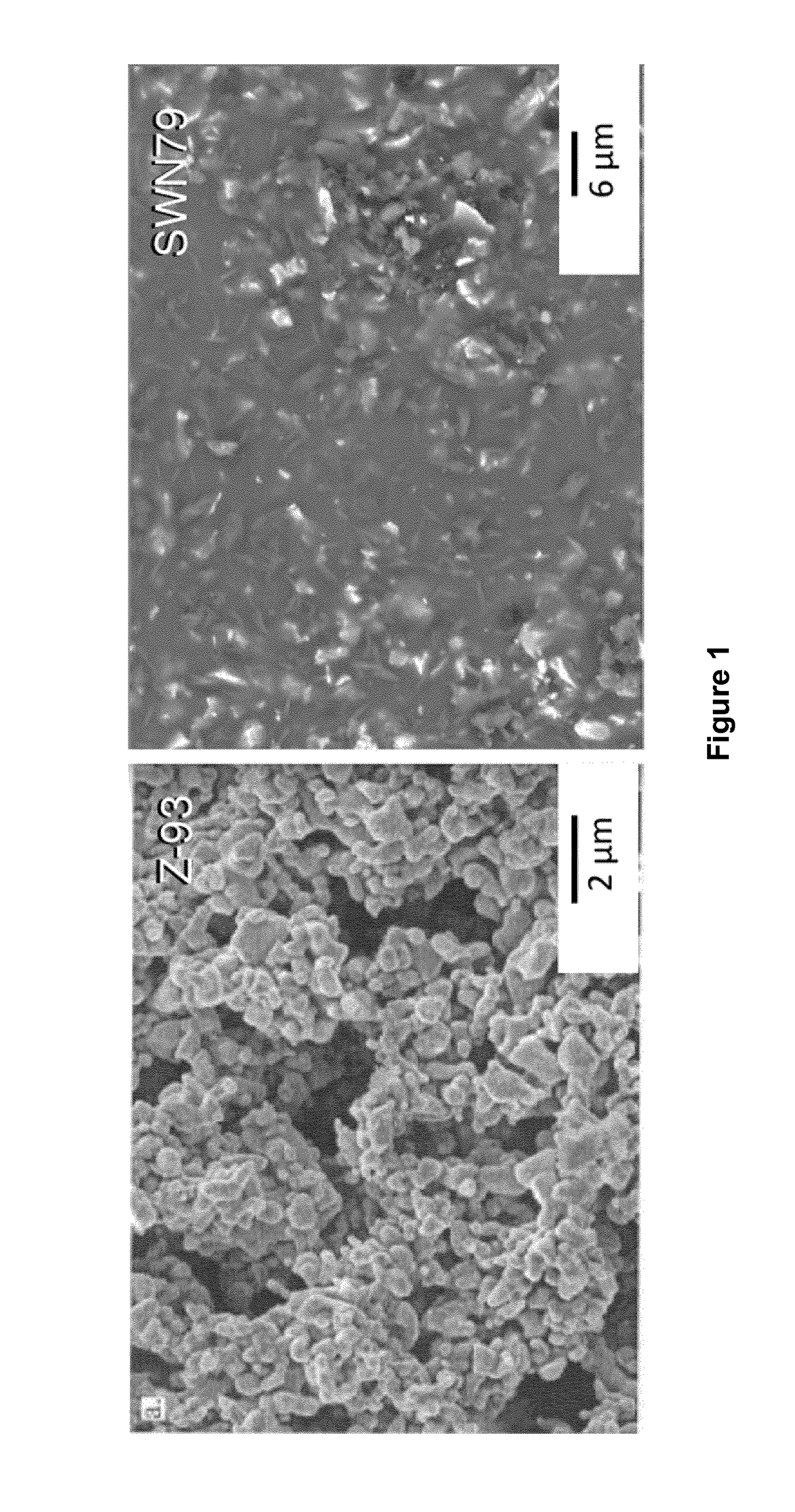
[0121]Curable coating compositions according to embodiments of the invention, which we refer to as SWN79, SWK66 and SWL40, were prepared in accordance with the m (wet %) of ingredients shown under Formulation A of Table 1.

[0122]

TABLE 1m (wet %)m (dry %)V (dry %)FORMULATION ASWN79Y2O330.0047.8133.10TCP10.0015.9417.64N7960.0036.2649.27SWK66Y2O330.0047.3032.59TCP10.0015.7717.37K6660.0036.9450.04SWL40Y2O337.5058.2543.89TCP12.5019.4223.39L4050.0022.3332.73FORMULATION BN79 MinY2O37.5017.009.56TCP2.505.675.09N7990.0077.3485.35K66 MinY2O37.5016.619.31TCP2.505.544.96K6690.0077.8585.73L40 MinY2O315.0039.0625.52TCP5.0013.0213.60L4080.0047.9260.89FORMULATION CN79 LowY2O315.0029.8018.17TCP5.009.939.68N7980.0060.2772.14K66 LowY2O315.0029.2717.77TCP5.009.769.47K6680.0060.9772.76L40 LowY2O326.2552.5537.87TCP8.7517.5220.18L4065.0029.9341.95FORMULATION DN79 HighY2O337.554.3839.60TCP12.518.1321.10N7950.027.4939.30K66 HighY2O337.553.9439.12TCP12.517.9820.85K6650.028.0840.04L40 HighY2O330.055.7641.19TCP...

example 2

[0129]Curable coating compositions, namely cured SWN79, SWK66 and SWL40, according to embodiments of the invention, were deposited onto metal samples and cured as follows.

Cured SWN79

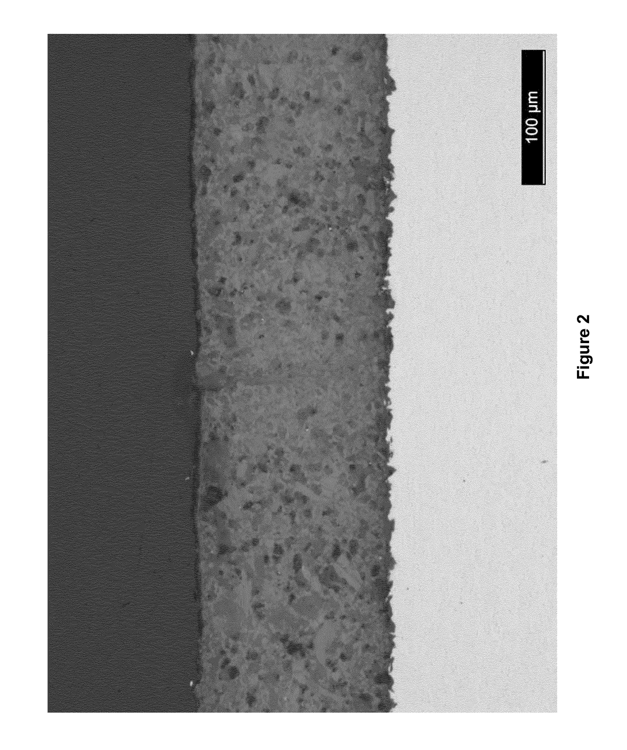
[0130]After mixing using the roller-ball mill as described in Example 1, the liquid SWN79 composition was sprayed onto the surface of a Grade V titanium (Ti6Al4V) substrate using a Trilogy™ AS spray gun, available from Nordson Corporation (Westlake, Ohio, USA). Spraying was carried out at a distance of 25 cm from the target surface until a coverage of 100 μm thickness was achieved. After spraying, the sprayed surface was covered with, but not in contact with, aluminium foil and allowed set overnight, i.e. for 12 to 16 hours at a temperature of 20° C. At this stage, the surface was no longer glossy in appearance, and the sample was transferred to a conventional fan assisted oven. The sample was heated to 250° C. in the oven as per the following thermal (cure) cycle:[0131]Heat from room temperature (20° C....

example 3

[0145]The attributes of the substrates coated with cured SWN79, cured SWK66 and cured SWL40, prepared in Example 2, were investigated as described below.

(A) Optical Absorbance

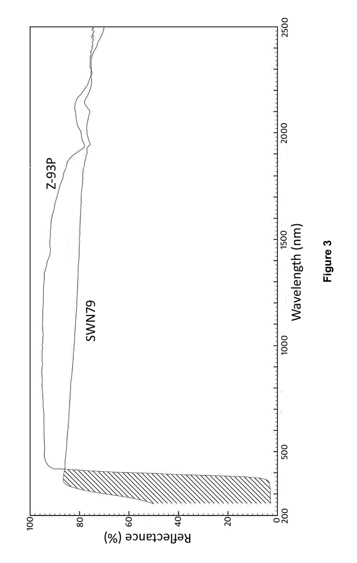
[0146]The diffuse reflectance R of the cured coatings SWN79 and SWL40 present on the titanium substrates prepared in Example 2 was measured in the UV / Vis / NIR range (250-2500 nm) using a Perkin Elmer Lambda 9 / 19 double beam spectrophotometer with a 150 mm integrating sphere attachment. Diffuse reflectance was measured against a Spectralon® reference to produce a reflectance trace (not shown) which was weighted against the Air Mass Zero (ASTM E490) solar irradiance spectrum. As the coated substrates were opaque, solar absorbance αs is simply: 1-R. The results are shown in Table 2.

[0147]

TABLE 2Cured SWN79Cured SWL40αs (%)thicknessαs (%)thickness17.3120 μm13.590 μm

[0148]Thus, the solar absorbance of the cured coatings SWN79 and SWL40 was found to be excellent, having αs of no greater than 0.2 (i.e. αs (%) no greate...


PUM

PropertyMeasurementUnit
particle sizeaaaaaaaaaa
solar absorptanceaaaaaaaaaa

Abstract

A curable coating composition comprising: (a) a silicate, such as sodium silicate, potassium silicate or lithium silicate; (b) a phosphate, such calcium phosphate, magnesium phosphate or sodium phosphate; and (c) a metal oxide, such as magnesium oxide, aluminum (III) oxide, scandium (III) oxide, yttrium (III) oxide, or zirconium oxide. Such curable coating compositions may be used as non-thermochromic (tailored based on expected operating environment) thermal control coating compositions for application to spacecraft and components thereof. As an alternative metal oxide component, for use in lower temperature applications, or in applications for which thermochromism at elevated temperatures is not a concern, the metal oxide may comprise zinc oxide. Also provided is a curable coating composition comprising: (a) a silicate (e.g. as above); (b) a phosphate (e.g. as above); and (c) a metal sulphate, such as a barium sulphate. Cured coatings are also provided, as are thermal control coatings, thermal control paints, and processes for making coated substrates.

Description

FIELD OF THE INVENTION[0001]This invention relates to curable coating compositions and cured coatings suitable for use as thermal control coatings for passive cooling applications. Examples of such applications include electronics and radiators for terrestrial applications, as well as space borne systems, including spacecraft, satellites and components thereof.BACKGROUND TO THE INVENTION[0002]Spacecraft are subjected to a wide range of thermal environments during their service. For example, in use, one side of a spacecraft may face in a direction away from the sun, while another side faces towards the sun. Thermal control is desirable because heat is radiated into space, which cools the spacecraft, but the spacecraft can simultaneously be heated intensively in direct sunlight. Active and passive temperature control techniques are therefore generally used to maintain the interior temperature of the spacecraft, which generally contains persons or sensitive instruments, within acceptab...

Claims


Application Information

Patent Timeline
Patent Type & Authority Patents(United States)
IPC IPC(8): C09D1/02C09D7/61C09D7/40C09D5/33
CPCC09D5/004C09D7/68C09D7/61C09D1/02C09D5/32
Inventor DOHERTY, KEVIN A. J.TWOMEY, BARRYSTANTON, KENNETH
Owner UNIV COLLEGE DUBLIN NAT UNIV OF IRELAND DUBLIN
Why Eureka
Try Eureka