
Electric storage device

a technology of storage device and electric current, which is applied in the direction of hybrid capacitors, capacitors, hybrid capacitor electrolytes, etc., can solve problems such as reliability, and achieve the effect of good high-temperature reliability and low-temperature characteristics

Active Publication Date: 2018-10-30
TAIYO YUDEN KK
View PDF12 Cites 3 Cited by
  • Summary
  • Abstract
  • Description
  • Claims
  • Application Information

AI Technical Summary

Benefits of technology

[0012]An object of the present invention, which was developed in light of the aforementioned problems, is to provide an electric storage device offering both good low-temperature characteristics and good high-temperature reliability.
[0022]According to the present invention, an electric storage device offering both good low-temperature characteristics and good high-temperature reliability can be provided.

Problems solved by technology

However, the reductive decomposition of γ-butyrolactone cannot be suppressed in a high-temperature state even when the lithium ion capacitor proposed by Patent Literature 1 is used, which leaves problems regarding reliability at high temperature, such as the film formed on the surface of the negative electrode inhibiting the migration of lithium ions, or the internal pressure of the cell rising due to generation of gas during reductive decomposition.
In addition, use of the electrolytic solution proposed by Patent Literature 2 still presents problems associated with the keeping of the device at high temperature for a long period of time, such as further formation of film on the surface of the negative electrode or decomposition of the electrolytic solution.

Method used


Image

  • Electric storage device
  • Electric storage device
  • Electric storage device

Examples


example 1

[0064]For the positive electrode, a slurry was prepared using PAS as an active material as well as commercially available carboxy methyl cellulose and styrene butadiene rubber as binders, and the slurry was applied onto a perforated aluminum foil to obtain a sheet-shaped positive electrode. For the negative electrode, a slurry was prepared using non-graphitizable carbon made of phenolic resin material as an active material as well as carboxy methyl cellulose and styrene butadiene rubber as binders, and the slurry was applied onto a perforated copper foil to obtain a sheet-shaped negative electrode. A cellulose separator was sandwiched between these electrodes, leader terminals were attached to a current collector by means of ultrasonic welding, and the components were rolled and secured with polyimide adhesive tape. A sealing rubber was attached to the element thus prepared and the element was vacuum-dried at approx. 180° C., after which lithium foil was attached to the negative ele...

examples 2 to 7

[0066]A lithium ion capacitor was prepared under the same method as in Example 1, except that the amount of additive was changed as shown in Table 1 over a range of 0.5 to 10 percent by weight.

example 8

[0067]A lithium ion capacitor was prepared under the same method as in Example 1, except that the type of additive was changed from bis(ethane sulfonate) methylene to bis(2,4,6-trimethyl benzene sulfonate) methylene (manufactured by Wako Pure Chemical Industries, Ltd., product name WEA-36, reduction potential of approx. 1.2 V (vs Li / Li+), denoted by “ADD-2” in Table 1).


PUM


Abstract

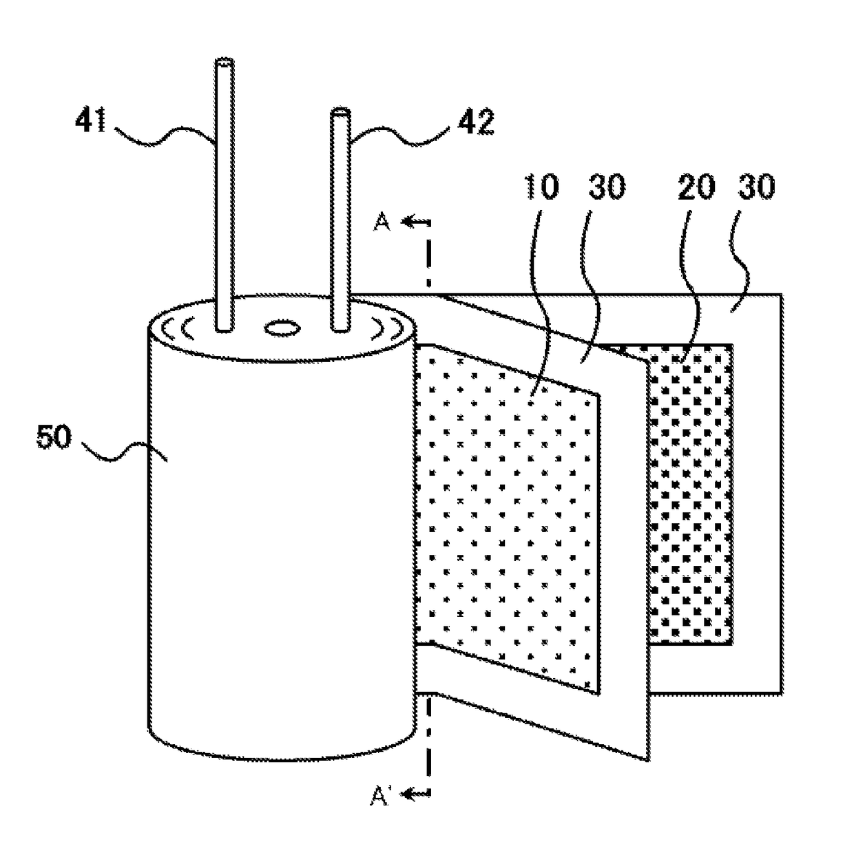
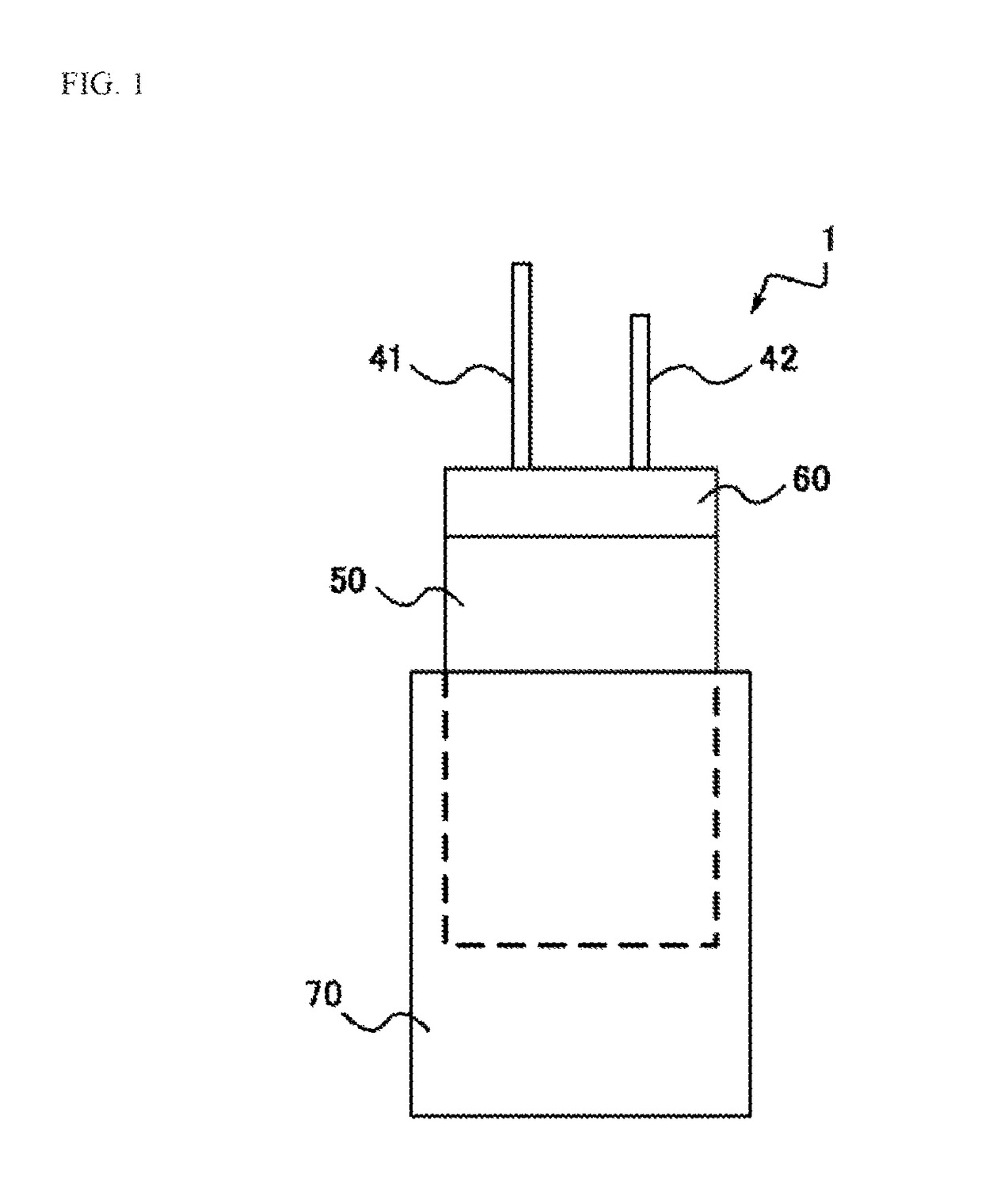
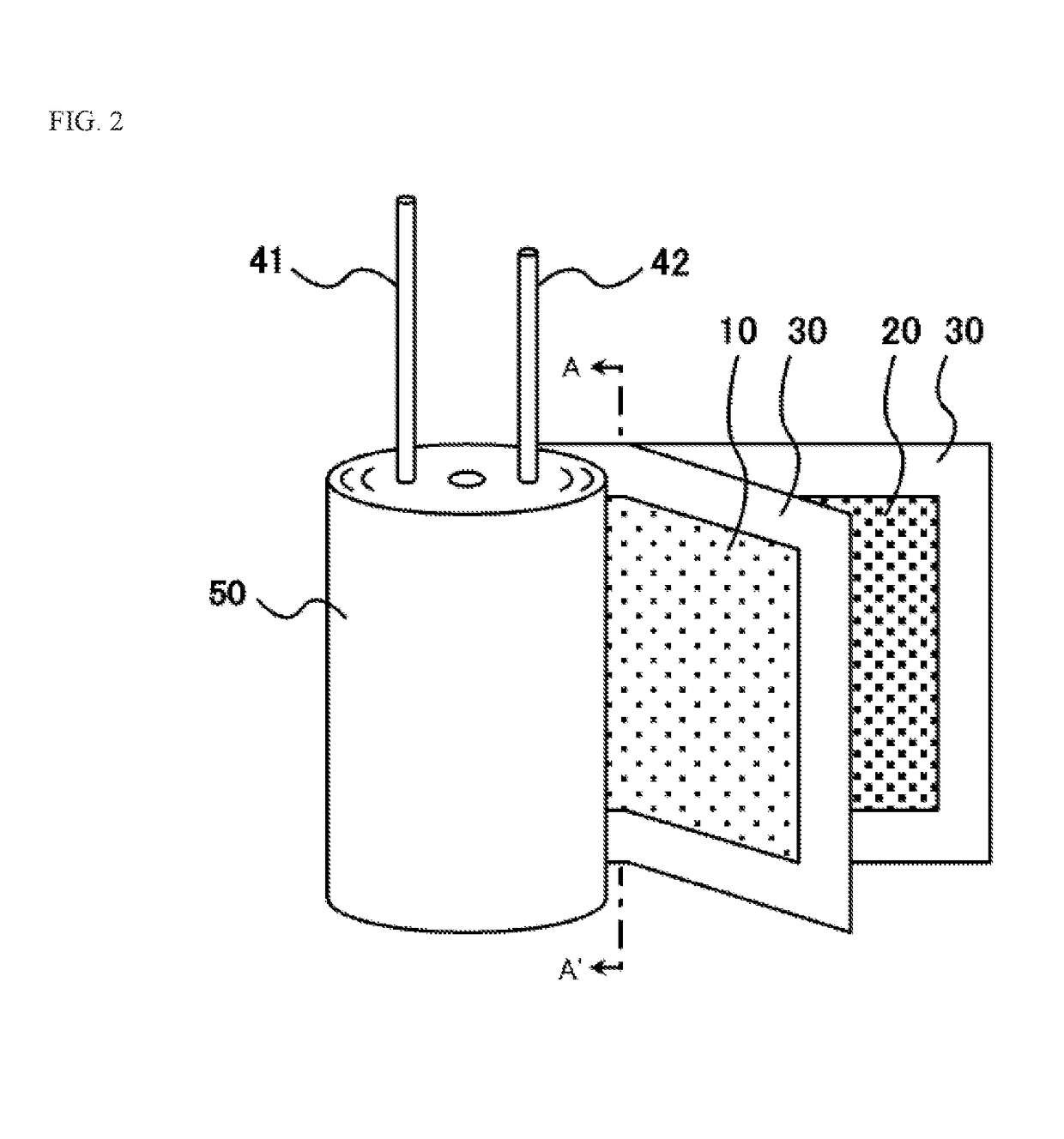
In an embodiment, an electric storage device 1 includes: an electric storage element 50 having a positive electrode and a negative electrode; a non-aqueous electrolytic solution constituted by a non-aqueous solvent primarily containing cyclic ester and cyclic carbonate ester, in which an electrolyte containing lithium salt is dissolved and to which a sulfonate ester derivative whose reduction potential is higher than that of the cyclic ester and cyclic carbonate ester is added; and an outer container 70 that stores the electric storage element 50 and non-aqueous electrolytic solution. The electric storage device can offer both good low-temperature characteristics and good high-temperature reliability.

Description

BACKGROUND[0001]Field of the Invention[0002]The present invention relates to an electric storage device with built-in, chargeable / dischargeable electric storage element.[0003]Description of the Related Art[0004]Known electric storage devices include electric double-layer capacitors, redox capacitors, lithium ion capacitors, lithium ion batteries, etc. In particular, lithium ion capacitors are drawing attention for their high level of energy density and high number of repeatable charge / discharge cycles which are made possible by combining a positive electrode similar to that of an electric double-layer capacitor or redox capacitor, and a negative electrode using a carbon material capable of occluding lithium ions.[0005]At the same time, recently lithium ion capacitors are required to maintain their capacitance in a low-temperature state, while ensuring reliability in a high-temperature state (such as 85° C.).[0006]In the area of improving low-temperature characteristics, Patent Liter...

Claims


Application Information

Patent Timeline
Patent Type & Authority Patents(United States)
IPC IPC(8): H01G11/58H01G11/64H01G11/60
CPCH01G11/60H01G11/64H01G11/58Y02E60/13H01G11/06
Inventor TSUZUKI, TAKEOKANO, KOJI
Owner TAIYO YUDEN KK
Learn More