Wafer carrier having thermal cover for chemical vapor deposition systems

a technology thermal cover, which is applied in the direction of chemical vapor deposition coating, coating, metallic material coating process, etc., can solve the problems of affecting device quality and production yield, so as to reduce temperature variability, reduce temperature non-uniformities, and reduce temperature variability

Inactive Publication Date: 2018-11-20
VEECO INSTR
View PDF75 Cites 230 Cited by
  • Summary
  • Abstract
  • Description
  • Claims
  • Application Information

AI Technical Summary

Benefits of technology

[0011]In various embodiments, a wafer carrier for use in a system for growing epitaxial layers on one or more wafers by CVD can comprise a top plate and a base plate, wherein the top plate covers the areas of the base plate not covered by one or more wafers, and wherein the presence of the top plate reduces temperature variability during CVD processing. The top plate can comprise the same material as the plurality of wafers, for example, silicon or sapphire; or the top plate can comprise a similar material as the plurality of wafers, for example, quartz, silicon carbide, solid silicon carbide, or aluminum nitride. In such embodiments, the base plate can generally be comprised of either silicon carbide or silicon carbide coated graphite. In various embodiments, temperature non-uniformities can be reduced when the top plate and the plurality of wafers are in the same horizontal plane within the wafer carrier. In other embodiments, temperature non-uniformities can be reduced when the top plate and the plurality of wafers are the same distance from the base plate. For example, the wafers and the top plate or top plates can rest on tabs or ring structures extending from the base plate, such that the gap distance between the wafers and the top surface of the wafer pocket is the same or similar as the gap distance between the top plates and the top surface of the base plate in the regions not occupied by wafers.
[0013]In some embodiments, the top plate can be comprised of a single piece of material, or the top plate can be comprised of one or more segments. Regardless, the top plate and the base plate can be fastened together, for example, using staples comprising molybdenum or similar materials. When fastened together, the top plate and the base plate can coordinately form a wafer pocket shaped from a compound radius of two or more intersecting arcs, or the top plate and the base plate can coordinately form a wafer pocket shaped from a compound radius of two or more non-intersecting arcs. In some embodiments, a wafer carrier configured of a top plate and a base plate as described herein can reduce temperature variability during CVD processing by a factor of about 2.0, about 2.5, about 3.0, about 3.5, about 4.0, about 4.5, about 5.0, about 5.5, about 6.0, about 6.5, about 7.0, about 7.5, about 8.0, about 8.5, about 9.0, about 9.5, or about 10.
[0014]Embodiments can also include a method for reducing temperature non-uniformities in a system for growing epitaxial layers on one or more wafers by chemical vapor deposition (CVD). The method can comprise assembling a wafer carrier comprising a top plate and a base plate, wherein the top plate covers the areas of the base plate not covered by one or more wafers, and wherein the presence of the top plate reduces temperature variability during CVD processing. The top plate and the base plate can be configured as described above, with the greatest reduction in temperature non-uniformities obtained when the top plate comprises the same material as the plurality of wafers, when the top plate and the plurality of wafers are the same distance from the base plate, and when the top plate and the plurality of wafers are the same thickness.
[0015]Advantageously, the use of a top plate and a base plate, wherein the top plate covers the areas of the base plate not covered by one or more wafers, as described herein, provides better uniformity in the thermal distribution on the surface of a wafer subjected to CVD processing. A number of other advantages will become apparent from the following Detailed Description.

Problems solved by technology

Even small variations in process conditions can adversely affect device quality and production yield.
If the deposited layer is an active, light-emitting layer of an LED structure, the emission wavelength of the LEDs formed from the wafer will also vary to an unacceptable degree.
Even each individual wafer can have temperature non-uniformities, i.e., cold spots and hot spots depending upon its geometrical position relative to the other wafers on the carrier.
This non-uniform temperature profile on the surface of the wafer, which is compounded by centripetal forces during rotation (i.e., the “proximity” effect), can significantly decrease semiconductor production yield.
Thus, a great deal of effort has been devoted to designing a system with features to minimize temperature variations during processing.

Method used


Image

  • Wafer carrier having thermal cover for chemical vapor deposition systems
  • Wafer carrier having thermal cover for chemical vapor deposition systems
  • Wafer carrier having thermal cover for chemical vapor deposition systems

Examples


Embodiment Construction

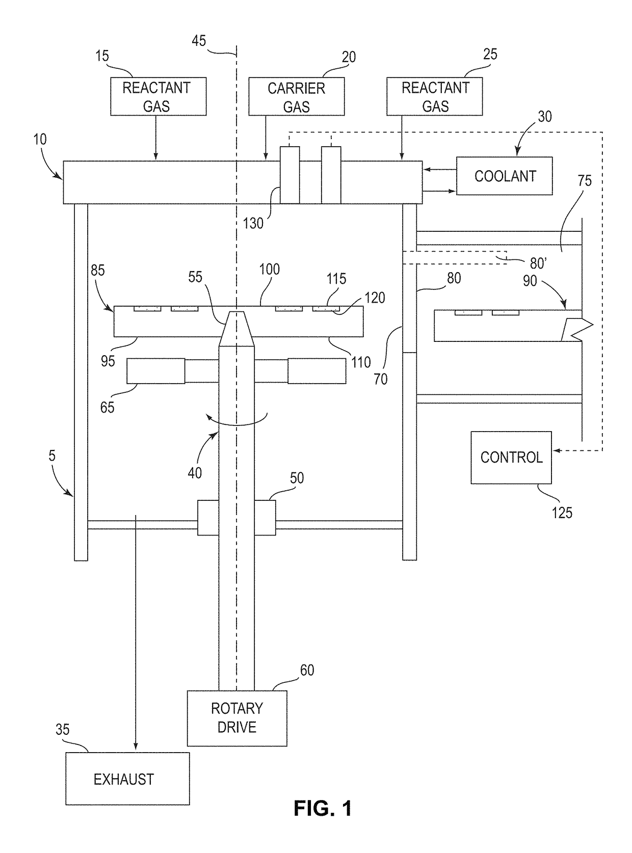
[0027]FIG. 1 illustrates a chemical vapor deposition apparatus in accordance with one embodiment of the invention. Reaction chamber 5 defines a process environment space. Gas distribution device 10 is arranged at one end of the chamber. The end having gas distribution device 10 is referred to herein as the “top” end of reaction chamber 5. This end of the chamber typically, but not necessarily, is disposed at the top of the chamber in the normal gravitational frame of reference. Thus, the downward direction as used herein refers to the direction away from gas distribution device 10; whereas the upward direction refers to the direction within the chamber, toward gas distribution device 10, regardless of whether these directions are aligned with the gravitational upward and downward directions. Similarly, the “top” and “bottom” surfaces of elements are described herein with reference to the frame of reference of reaction chamber 5 and gas distribution device 10.

[0028]Gas distribution d...


PUM

PropertyMeasurementUnit
temperatureaaaaaaaaaa
thickaaaaaaaaaa
diameteraaaaaaaaaa

Abstract

The invention relates generally to semiconductor fabrication technology and, more particularly, to chemical vapor deposition (CVD) processing and associated apparatus for addressing temperature non-uniformities on semiconductor wafer surfaces. Embodiments include a wafer carrier for use in a system for growing epitaxial layers on one or more wafers by CVD, the wafer carrier comprising a top plate and base plate which function coordinately to reduce temperature variability caused during CVD processing.

Description

PRIOR APPLICATION[0001]This Application claims priority to U.S. Provisional Application No. 61 / 920,943 filed Dec. 26, 2013, the content of which is incorporated by reference herein.FIELD OF THE INVENTION[0002]The invention relates generally to semiconductor fabrication technology and, more particularly, to chemical vapor deposition (CVD) processing and associated apparatus having features for reducing temperature non-uniformities on semiconductor wafer surfaces.BACKGROUND OF THE INVENTION[0003]In the fabrication of light-emitting diodes (LEDs) and other high-performance devices such as laser diodes, optical detectors, and field effect transistors, a chemical vapor deposition (CVD) process is typically used to grow a thin film stack structure using materials such as gallium nitride over a sapphire or silicon substrate. A CVD tool includes a process chamber, which is a sealed environment that allows infused gases to be deposited upon the substrate (typically in the form of wafers) to ...

Claims


Application Information

Patent Timeline
Patent Type & Authority Patents(United States)
IPC IPC(8): H01L21/673C23C16/46C23C16/458H01L21/687
CPCH01L21/67333C23C16/4584C23C16/46H01L21/68764H01L21/68771H01L21/68735Y10T29/49837Y10T29/49826
Inventor GURARY, ALEXANDER I.ARMOUR, ERIC
Owner VEECO INSTR
Why Eureka
Try Eureka