
Alignment film detecting device and alignment film detecting method

a detection device and alignment film technology, applied in the field of display technology, can solve the problems of reducing efficiency, adversely affecting alignment performance, prolonged period of spraying vapor for detection, etc., and achieve the effects of accurate determination, low recognition rate, and improved detection efficiency

Inactive Publication Date: 2018-11-27
BOE TECH GRP CO LTD +1
View PDF12 Cites 0 Cited by
  • Summary
  • Abstract
  • Description
  • Claims
  • Application Information

AI Technical Summary

Benefits of technology

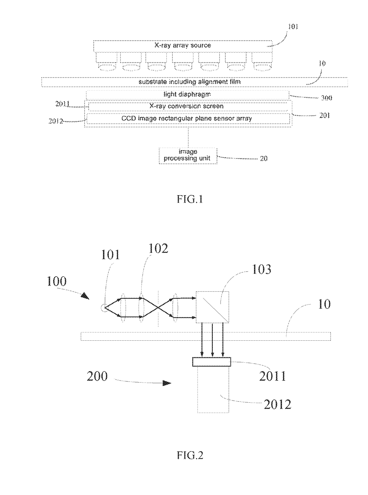
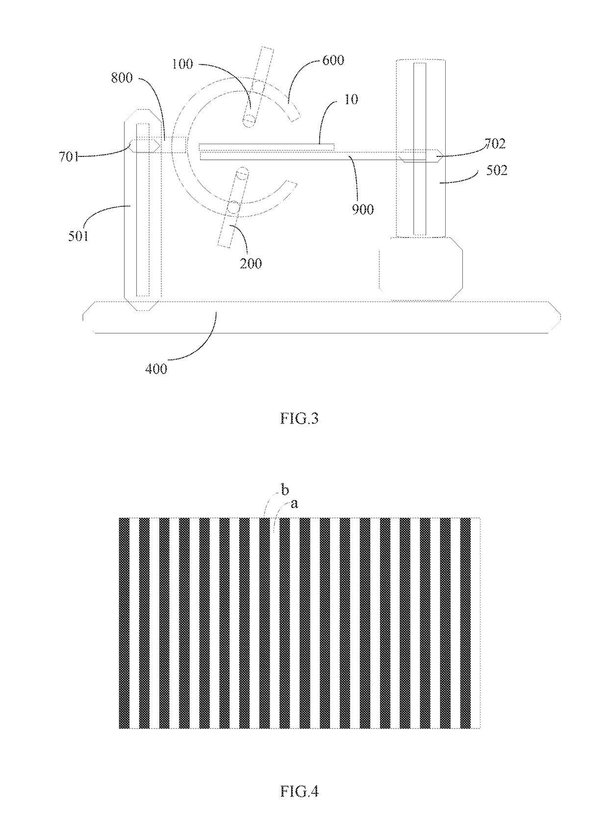
This patent is about a device and method for detecting alignment films on substrates using X-rays. The device includes a light diaphragm to adjust the intensity of X-rays transmitted through the substrate, which helps stabilize the radiation amount received by the X-ray sensitive lens. The device can accurately detect and measure the width and depth of each alignment groove in the alignment film, without the need for a separate static electricity elimination process. Additionally, the device can detect small cracks within the substrate and improve product quality control. The method allows for quick detection and adjustment of the rubbing device, resulting in improved yield of products.

Problems solved by technology

During the process of forming the alignment film, since the rubbing cloth may have defect such as uneven width, foreign substances being adhered to a surface, an affection by impurities during the process of rubbing for forming the grooves or etc., the grooves on the alignment film formed by such processes may have a direction, a shape, a depth and etc. that deviate from a desired direction, a desired shape, a desired depth and etc. respectively, namely a rubbing mura is generated, so that the alignment performance is adversely affected.
Firstly, the water vapor is sprayed and adhered to the glass substrate and the surface of the alignment film. Thus, during the process of forming the water droplets, some of the formed water droplets continue to disappear due to facts of air movement, evaporation and so on, so that a period of spraying the vapor for the detection is prolonged, and the efficiency is lowered.
Secondly, the efficiency of the above method for detecting whether there is the defect in the grooves on the alignment film is low because it is implemented manually. In addition, the credibility of the detection result may be low because different operators may have different standards for the detection by their eyes respectively.
Thirdly, when the glass substrate and the alignment film are large, some regions in the glass substrate and the alignment film may be unreachable by the vapor spray nozzle hold by the operator, so that the defect in grooves in these regions of the alignment film is undetectable.
Fourthly, the vapor spray nozzle is typically in direct connection with a water tank being heated. As a result, when a water level in the tank is high, it is possible that some water droplets in the tank are transmitted to the vapor spray nozzle and sprayed to the alignment film, and thus the subsequent process is adversely affected.
Fifthly, the grooves on the alignment film are required to be smaller as a capability for detecting the alignment grooves in the TFT LCD is becoming stronger. Since an evenness of the water droplets formed on the surfaces of the glass substrate and the alignment film is poor and observation limitation on human eyes, the above vapor detection method cannot satisfy the requirement of detecting the defect in the grooves on the alignment film of the TFT LCD which has a strong detection capability for detecting the alignment grooves.
Furthermore, the above vapor detection method is implemented manually, so that the position of the defect in the rubbing cloth generally cannot be accurately determined by the manual computation, and thus it is impossible that the defect in the rubbing cloth is eliminated by one-time positioning and repairing.
As a result, the above process has to be repeated several times. If the defect in the rubbing cloth still has not been eliminated by repeating the above process several times, the rubbing cloth has to be replaced by a new one, which is expensive and laborious, and also reduce utilization of the production line.

Method used


Image

  • Alignment film detecting device and alignment film detecting method
  • Alignment film detecting device and alignment film detecting method
  • Alignment film detecting device and alignment film detecting method

Examples


Embodiment Construction

[0047]The present disclosure will be described hereinafter in conjunction with the drawings and embodiments. The following embodiments are for illustrative purposes only, but shall not be used to limit the scope of the present disclosure.

[0048]In order to make the objects, the technical solutions and the advantages of the present disclosure more apparent, some technical solutions of the present disclosure will be described hereinafter in a clear and complete manner in conjunction with the drawings and embodiments. Obviously, the following embodiments are merely a part of, rather than all of, the embodiments of the present disclosure, and based on these embodiments, a person skilled in the art may obtain the other embodiments, which also fall within the scope of the present disclosure.

[0049]Unless otherwise defined, any technical or scientific term used herein shall have the common meaning understood by a person of ordinary skills. Such words as “first” and “second” used in the speci...


PUM

PropertyMeasurementUnit
image processingaaaaaaaaaa
depthaaaaaaaaaa
widthaaaaaaaaaa

Abstract

The present disclosure provides in some embodiments an alignment film detecting device including: an imaging unit configured to obtain image information of the alignment grooves on the alignment film of the substrate; and an image processing unit configured to determine whether there is a defect in the alignment grooves on the alignment film based on the image information. According to the alignment film detecting device and the alignment film detecting method provided the present disclosure, the defect of the alignment film on the substrate may be detected, and the image information of the alignment grooves on the alignment film of the substrate may be obtained by the imaging unit, and a recognizing process may be implemented by the image processing unit based on the image information, so that it may accurately determine whether there is a defect in the alignment grooves. As compared with a method of manually detecting the defect in the alignment grooves by vapor in a conventional alignment film detecting technique, it may overcome disadvantages of manually detecting the defect in the alignment grooves of the substrate, such as low recognition rate, being vulnerable to false detection, and inefficient detection, so as to improve detection efficiency as well as accuracy and credibility of the detection result.

Description

CROSS REFERENCE OF RELATED APPLICATION[0001]The present application claims the priority of Chinese patent application No. 201510257769.6 filed on May 19, 2015, the disclosure of which is incorporated herein by reference in its entirety.TECHNICAL FIELD[0002]The present disclosure relates to the field of display technology, in particular to an alignment film detecting device and an alignment film detecting method.BACKGROUND[0003]Alignment films are arranged on an array substrate and a color filer substrate of a thin film transistor liquid crystal display (TFT-LCD) respectively, and grooves are arranged on each alignment film in a predetermined direction and configured for causing liquid crystal molecules to be arranged in the direction of the grooves in a condition that the liquid crystal molecules are not affected by an electric field. The alignment film having an alignment function is generally formed by a polyimide (PI) film in a process of: rubbing a PI film coated and solidified ...

Claims


Application Information

Patent Timeline
Patent Type & Authority Patents(United States)
IPC IPC(8): G02F1/13G06T7/00G01N23/18
CPCG02F1/13G01N23/18G06T7/0006G06T2207/30121G01N2223/646G06T2207/10116G01N2223/611G02F1/1309G02F1/133784G01N23/083
Inventor JING, YANGKUNJIANG, CHANGJUN
Owner BOE TECH GRP CO LTD
Learn More