Naphtyl based high index hydrophobic liquids and transmission recovery agents for liquid lens formulations

a technology of transmission recovery agent and hydrophobic liquid, which is applied in the field of liquid lens, can solve the problems of slow evaporation, degrade both the oil liquid phase and the electrowetting device itself, and water volatility

Active Publication Date: 2019-05-21
CORNING INC
View PDF23 Cites 6 Cited by
  • Summary
  • Abstract
  • Description
  • Claims
  • Application Information

AI Technical Summary

Problems solved by technology

However, among the drawbacks of water based conductive phases are the volatility of water, particularly when the electrowetting device is used in warm or hot environments where risks of corrosion can degrade both the oil liquid phase and the electrowetting device itself.
Additionally, for liquid lens applications, the use of water frequently leads to its slow evaporation over time and leakage of water outside the liquid lens.
As a consequence, when too much water is lost, an air bubble will appear in the liquid lens, which renders the lens ineffective.

Method used


Image

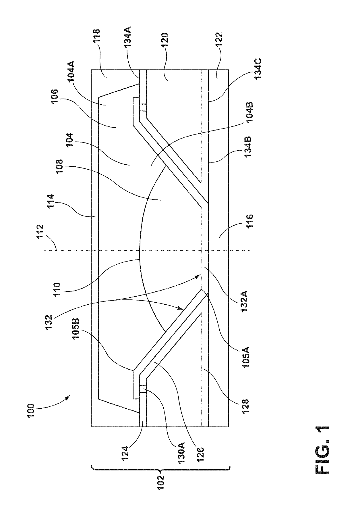
  • Naphtyl based high index hydrophobic liquids and transmission recovery agents for liquid lens formulations
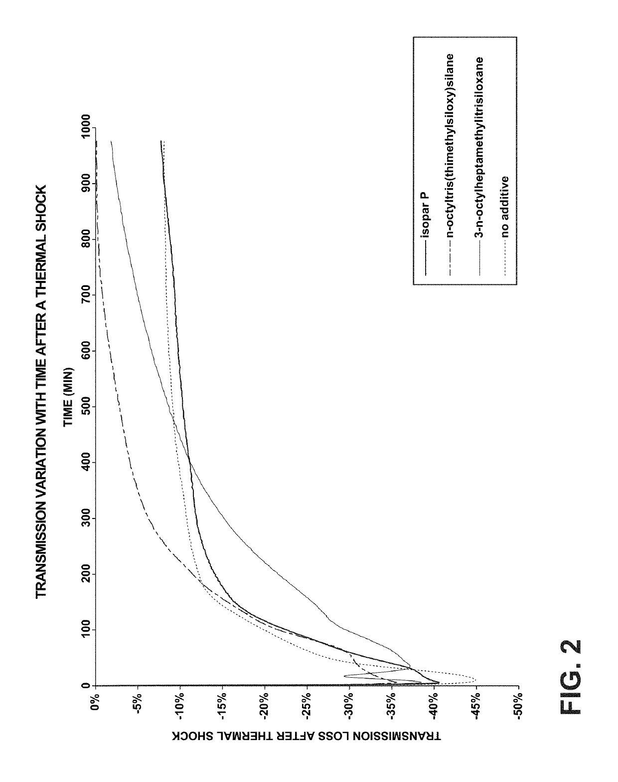
  • Naphtyl based high index hydrophobic liquids and transmission recovery agents for liquid lens formulations
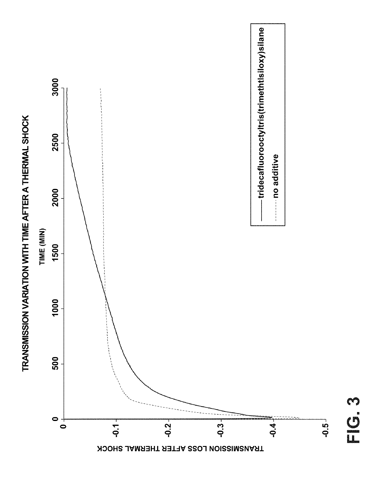
  • Naphtyl based high index hydrophobic liquids and transmission recovery agents for liquid lens formulations

Examples


formulation example 1

[0095]The electrowetting optical device of Example 1 includes: a non-conductive liquid having 75.5% w / w / naphtyltriethylgermane, 15% w / w n-octyltris(trimethylsiloxy) silane, and 9.5% w / w Parrafin oil; and a conductive liquid having 60% w / w monopropylene glycol, 38.8% w / w water, and 1.2% w / w sodium bromide.

[0096]

NON-CONDUCTIVE LIQUIDCONDUCTIVE LIQUID% in weightcompound% in weightcompound75.5%Naphtyltriethylgermane  60%Monopropylene glycol  15%n-octyltris 38.8%Water(trimethylsiloxy) silane 9.5%Paraffin oil 1.2%Sodium bromideDensity: 1.05 g / cm3Density (20° C.): 1.05 g / cm3Index (589.3 nm-20° C.): 1.54Index (589.3 nm-20° C.): 1.40Viscosity (20° C.): 8.3 cStViscosity (20° C.): 9.9 cSt

formulation example 2

[0097]The electrowetting optical device of Example 2 includes: a non-conductive liquid having 80% w / w / naphthylphenylsulfure and 20% w / w phenyltris(trimethylsiloxyl)silane; and a conductive liquid having 10% w / w 1,3-propandiol, 52% w / w water, 35% w / w ethylene glycol, and 3% w / w potassium acetate.

[0098]

NON-CONDUCTIVE LIQUIDCONDUCTIVE LIQUID% in weightcompound% in weightcompound80%Naphthylphenylsulfur10%1,3-propandiol20%Phenyltris35%Ethylene glycol(trimethylsiloxyl) silane52%Water 3%Potassium acetateDensity: 1.09 g / cm3Density: 1.07 g / cm3Index (589.3 nm-20° C.): 1.63Index (589.3 nm-20° C.): 1.38Viscosity (20° C.): 20 cStViscosity (20° C.): 3.8 cSt

formulation example 3

[0099]The electrowetting optical device of Example 3 includes: a non-conductive liquid having 100% w / w naphtyltrimethylsilane; and a conductive liquid having 99% w / w water, and 1% w / w potassium acetate.

[0100]

NON-CONDUCTIVE LIQUIDSCONDUCTIVE LIQUIDS% in weightcompound% in weightcompound100%1-Naphtyltrimethylsilane99%Water 1%Potassium acetateDensity: 1.01 g / cm3Density: 1.00 g / cm3Index (589.3 nm-20° C.): 1.58Index (589.3 nm-20° C.): 1.34Viscosity (20° C.): 8.1 cStViscosity (20° C.): 1.0 cSt


PUM


Abstract

An electrowetting optical device is provided. The electrowetting optical device includes a conductive liquid and a non-conductive liquid. The non-conductive fluid includes a naphthalene based compound having Formula (I), Formula (II), and / or Formula (III):where R1, R2, and R3 are individually alkyl, aryl, alkoxy, or aryloxy groups; X includes carbon, silicon, germanium, tin, lead, and combinations thereof; and Z includes oxygen, sulfur, selenium, tellurium, polonium, and combinations thereof. The conductive liquid may additionally include a transmission recovery agent having Formula (IV) and / or Formula (V):where R4 is an alkyl, fluoroalkyl, aryl, alkoxy, or aryloxy group. The electrowetting optical device additionally includes a dielectric surface in contact with both the conductive and non-conductive liquids where the conductive and non-conductive liquids are non-miscible.

Description

CROSS-REFERENCE TO RELATED PATENT APPLICATION[0001]This application claims the benefit of U.S. Application No. 62 / 646,809 filed on Mar. 22, 2018 and Application No. 62 / 658,757 filed on Apr. 17, 2018, which is incorporated herein by reference in their entirety.FIELD OF THE DISCLOSURE[0002]The disclosure relates to liquid lenses and, more particularly, liquid lenses using high index hydrophobic liquids formulated using naphthyl based compounds and transmission recovery agents.BACKGROUND[0003]Conventional electrowetting based liquid lenses are based on two immiscible liquids disposed within a chamber, namely an oil and a conductive phase, the latter being water based. The two liquid phases typically form a triple interface on an isolating substrate comprising a dielectric material. Varying an electric field applied to the liquids can vary the wettability of one of the liquids relative to walls of the chamber, which has the effect of varying the shape of a meniscus formed between the tw...

Claims


Application Information

Patent Timeline
Patent Type & Authority Patents(United States)
IPC IPC(8): G01C5/04G09G3/34G02B26/00G02B26/08
CPCG02B26/005G09G3/348G01C5/04G02B26/004G09G3/3433G02B26/08
Inventor BURGER, BENJAMIN JEAN-BAPTISTE FRANCOISVASSEUR, GERALDINE MALET
Owner CORNING INC
Why Eureka
Try Eureka