
High capacity solid state composite cathode, solid state composite separator, solid-state rechargeable lithium battery and methods of making same

a rechargeable lithium battery, high-capacity technology, applied in the direction of cell components, final product manufacturing, sustainable manufacturing/processing, etc., can solve the problems of affecting battery performance, cracks to be formed in the final product, and inhibiting the optimum transport of ions

Active Publication Date: 2019-06-25
JOHNSON IP HLDG LLC
View PDF259 Cites 1 Cited by
  • Summary
  • Abstract
  • Description
  • Claims
  • Application Information

AI Technical Summary

Benefits of technology

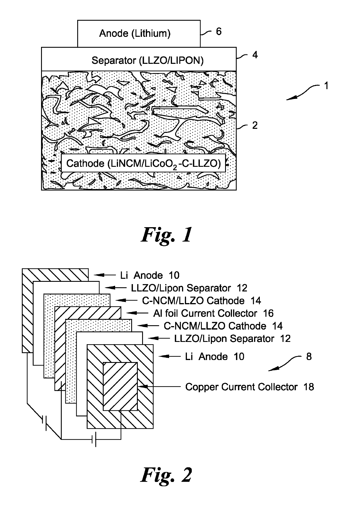
The invention offers batteries with higher capacity, deeper access to the cathode, lower cost, and temperature processing. Additionally, the batteries have smooth surface cathodes that result in better uniformity and coverage by the solid electrolyte separator film. Finally, the batteries can be scaled up to large size.

Problems solved by technology

However, some solid ionically conductive materials have flaws, such as cracks in the material, which may adversely impact battery performance.
Solid ionically conductive materials are often produced from precursors via a process that may cause cracks to be formed in the final product.
Such cracks may inhibit the optimum transport of ions through the solid electrolyte.
In addition, cracks may provide pathways for the transport of electrons between electrodes, thereby producing short-circuits that may cause the cell to fail.
Because lithium atoms generally have low diffusion coefficients in active cathode materials, the capacity of thick layer cathodes can only be shallowly, not fully, accessed during charge / discharge cycles of the battery.
As a result, lithium ions can only move a limited distance from their entrance point into the cathode material at reasonable charge discharge rates.
This shallow access dramatically reduces the volumetric and gravimetric energy density of the resulting batteries.
Current thin film solid-state lithium-ion battery technology employs expensive substrates, including noble metals, and uses expensive sputtering processes to form the cathode material coatings.

Method used


Image

  • High capacity solid state composite cathode, solid state composite separator, solid-state rechargeable lithium battery and methods of making same
  • High capacity solid state composite cathode, solid state composite separator, solid-state rechargeable lithium battery and methods of making same

Examples


example 1

on of Composite Cathode and Lithium Battery

[0089]A dried cathode material (NCM) (obtained from Pred Materials International (New York, N.Y.)) was washed in isopropanol and dried at 200° C. in an ozone-rich air environment for about two hours. A LLZO sol gel precursor solution was prepared by dissolving about 4.5 grams of a lanthanum methoxyethoxide solution (about 12% by weight in methoxyethanol), about 0.65 gram of lithium butoxide and about 0.77 gram of a zirconium butoxide solution (about 80% by weight in butanol) in about 5 grams of methoxyethanol (all chemicals obtained from Gelest, Inc. (Morrisville, Pa.) or Alfa Aesar). The thoroughly-mixed precursor solution was left in a bottle in an inert environment for about 1 to 1.5 hours to help facilitate substantially complete dissolution of the lithium butoxide.

[0090]In an inert environment, a slurry was prepared by combining 6 g of the dried cathode material, 1.2 g LAGP (electrolyte powder), 6 ml of the LLZO sol-gel precursor solut...

example 2

on of Composite Separator

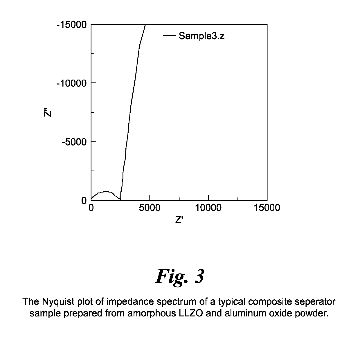
[0093]Aluminum oxide powder from Sigma-Aldrich in the form of nanoparticles (size ˜60 nm) was dried at about 150° C. under vacuum for about 24 h. About 2 g of the dried Al2O3 powder was mixed with 2 ml of LLZO sol gel precursor solution as described in Example 1 into an energy milling jar. The jar was air tight sealed in the inert environment and was energy milled for about 80 min. A 45-micron thick aluminum foil was prepared by wiping with isopropanol and drying at about 80° C. for about one hour. The homogeneously milled slurry was cast onto the clean and dried foil inside an ozone-rich (at least 0.05 ppm) and low humidity (less than about 30 percent relative humidity) air environment to form a sheet. The sheet was let to dry and cure for about one hour in the ozone-rich and low humidity air environment. Subsequently, the sheet was compacted using a clean roller inside the same air environment. Thereafter, one square inches pieces were cut from the sheet a...


PUM

PropertyMeasurementUnit
temperatureaaaaaaaaaa
thicknessaaaaaaaaaa
thicknessaaaaaaaaaa

Abstract

A high capacity solid state composite cathode contains an active cathode material dispersed in an amorphous inorganic ionically conductive metal oxide, such as lithium lanthanum zirconium oxide and / or lithium carbon lanthanum zirconium oxide. A solid state composite separator contains an electronically insulating inorganic powder dispersed in an amorphous, inorganic, ionically conductive metal oxide. Methods for preparing the composite cathode and composite separator are provided.

Description

CROSS-REFERENCE TO RELATED APPLICATION[0001]This application is a Section 371 U.S. National-Stage Application of International Application No. PCT / US2013 / 028672, filed Mar. 1, 2013, which was published on Sep. 6, 2013, under International Publication No. WO 2013 / 131005, and which derives priority from U.S. Patent Application No. 61 / 605,241, filed Mar. 1, 2012 and U.S. Patent Application No. 61 / 606,840 filed Mar. 5, 2012, the disclosures of which are all incorporated herein by reference in their entireties.BACKGROUND OF THE INVENTION[0002]A battery cell is a particularly useful article that provides stored electrical energy which can be used to energize a multitude of devices, including portable devices that require an electrical power source. A battery cell, which is often referred to, somewhat inaccurately, in an abbreviated form as a “battery,” is an electrochemical apparatus typically formed from at least one electrolyte (also referred to as an “electrolytic conductor”) disposed ...

Claims


Application Information

Patent Timeline
Patent Type & Authority Patents(United States)
IPC IPC(8): H01M2/14H01M2/16H01M10/052H01M10/0585H01M10/0562H01M4/62H01M4/525H01M4/505H01M4/1391H01M4/131H01M4/04H01M4/36H01M4/136H01M4/58H01M4/485H01M4/02H01M50/403H01M50/431H01M50/443H01M50/497
CPCH01M2/145H01M2/1686H01M4/0404H01M4/0435H01M4/0471H01M4/131H01M4/136H01M4/1391H01M4/364H01M4/485H01M4/505H01M4/525H01M4/5825H01M4/621H01M4/625H01M10/052H01M10/0562H01M10/0585H01M2/1646H01M2300/0068H01M2004/028H01M4/23H01M4/665H01M6/187H01M10/054H01M50/431H01M50/443H01M50/497H01M50/403Y02P70/50Y02E60/10H01M4/13H01M4/139H01M4/48H01M4/62H01M2004/021
Inventor THOKCHOM, JOYKUMAR S.BABIC, DAVORINJOHNSON, LONNIE G.ALLIE, LAZBOURNE ALANZOJOHNSON, DAVID KETEMARAUCH, WILLIAM
Owner JOHNSON IP HLDG LLC
Learn More