Dynamic gate drive system and control method

a gate drive and control method technology, applied in power conversion systems, voltage/temperature variation compensation, reliability increasing modifications, etc., can solve problems such as limiting the maximum efficiency and phase current level

Active Publication Date: 2019-12-10
GM GLOBAL TECH OPERATIONS LLC
View PDF2 Cites 3 Cited by
  • Summary
  • Abstract
  • Description
  • Claims
  • Application Information

AI Technical Summary

Benefits of technology

[0009]In this non-limiting embodiment, a Gate driver IC is connected to the Gate terminals of each of the buffer switches. The microcontroller is configured, responsive to a received set of circuit measurements, to access a lookup table indexed by the circuit measurements, and then to select switching control values and Gate resistor identities based on the circuit measurements. The microcontroller transmits binary (on/off) switching control signals and a G

Problems solved by technology

Such approaches tend to limit the maximum efficiency and level of phase curr

Method used


Image

  • Dynamic gate drive system and control method
  • Dynamic gate drive system and control method
  • Dynamic gate drive system and control method

Examples


Embodiment Construction

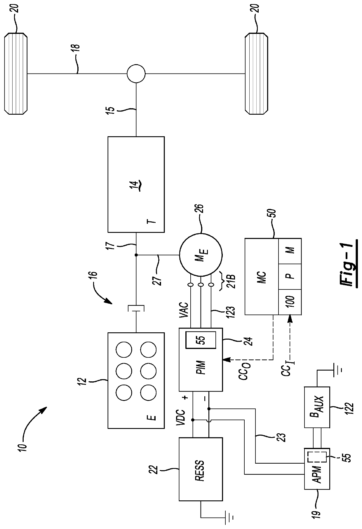
[0031]Referring to the drawings, wherein like reference numbers refer to the same or like components in the several Figures, a powertrain system 10 is depicted schematically in FIG. 1. For illustrative purposes, the powertrain system 10 is shown as part of a motor vehicle. However, the present teachings may be applied in other mobile or stationary electrical systems in which high-speed electrical switching operations are performed. Those of ordinary skill in the art will appreciate that the above-noted switching operations are performed in various types of vehicles, e.g., motor vehicles, rail vehicles, aircraft, and watercraft, in drive systems of mobile platforms and robotic applications, as well as in powerplants, hoist systems, conveyors, plant equipment, etc. The powertrain system 10 of FIG. 1 shown in a motor vehicle context is therefore just one possible example application, which is used hereinafter for illustrative consistency without limiting the scope of the disclosure to ...


PUM


Abstract

A switching circuit includes a semiconductor switch having a Gate terminal, and includes first, second, third, and fourth Gate resistors. The Gate resistors have upstream and downstream ends relative to a location of the semiconductor switch or a driven load. The downstream ends connect to the Gate terminal. First, second, third, and fourth buffer switches have Gate terminals and Source terminals, with the Source terminals connected to the upstream ends of the first, second, third, and fourth Gate resistors, respectively. An optional Gate driver integrated circuit (IC) connects to the Gate terminals of the buffer switches. A microcontroller, responsive to circuit measurements, selects switching control values and Gate resistor identities based on the measurements, and transmits switching control signals and a Gate resistor selection signal to select on/off states of the buffer switches and an optimum switching speed for the semiconductor switch.

Description

INTRODUCTION[0001]Solid-state semiconductor switches are used in a wide variety of power electronic devices. In high-power applications, for instance, semiconductor switches are integral to the internal switching construction of power inverter modules, voltage converters, power amplifiers, and switching power supplies. In an electrical circuit having a polyphase electric machine, the individual phase legs of the machine's alternating-current (AC) side are electrically connected to a corresponding pair of semiconductor switches of a power inverter module. A direct-current (DC) side of the power inverter module is electrically connected to positive and negative rails of a DC voltage bus, which in turn is connected to a multi-cell battery pack or another DC power supply.[0002]In a power inversion process, pulse width modulation, pulse density modulation, delta-sigma modulation, pulse-frequency modulation, or other application-suitable binary (on / off) switching control signals are trans...

Claims


Application Information

Patent Timeline
IPC IPC(8): H03K17/687H03K19/003
CPCH03K17/6871H03K19/00369H02M7/53871H02M7/5395H02P27/085H03K17/163H03K17/168
Inventor ALAM, MOHAMMED KANWAR, MOHAMMAD N.KADRY, SYED M.BASHER, KOROBITAMAI, GOROCAWTHORNE, WILLIAM R.VADULA, SUBRAMANIAN
Owner GM GLOBAL TECH OPERATIONS LLC
Why Eureka
Try Eureka