Metal chalcogenides for pseudocapacitive applications

a technology of metal chalcogenides and pseudocapacitive devices, which is applied in the field of pseudocapacitive devices, can solve the problems of low power density and slow rate, low energy density of eldcs compared to batteries, and the desirable property of mossub>2 /sub>has not been fully utilized in li-ion battery applications, etc., and achieves high porousness, high electrical conductivity, and fast rate

Active Publication Date: 2020-08-04
RGT UNIV OF CALIFORNIA
View PDF3 Cites 0 Cited by
  • Summary
  • Abstract
  • Description
  • Claims
  • Application Information

AI Technical Summary

Benefits of technology

[0017]The highly defected structure can be used, for example, as a component of an electrode that also includes a carbon derivative, and a binder, which are intermixed to form the electrode. The carbon derivative can be, for example, carbon fibers, or carbon black, or carbon black and carbon fibers. The binder can be, for example, polyacrylic acid. The resultant composite electrode is highly porous and highly electronically conductive, and is suitable for use in devices such as symmetric capacitors, asymmetric capacitors, rocking chair batteries, and other devices. Porous electrode architectures that are highly electronically conductive represent an effective design strategy to maintain the fast rates inherent to pseudocapacitive active materials.
[0018]In one embodiment, this disclosure describes the synthesis of about 10 nm to about 75 nm highly defected MoS2 nanocrystals with expanded atomic spacing and its use in high rate energy applications. In one embodiment, the MoS2 nanoparticles are synthesized through a two-step method that is both economical and scalable.

Problems solved by technology

Traditional Li-ion battery electrodes offer high energy density storage by utilizing reversible redox reactions, but slow ionic diffusion leads to long charging times (about 1 hour) resulting in low power densities and slow rates.
However, ELDCs have low energy densities compared to batteries since they do not involve redox reactions.
Though this 1T-phase has been exploited in hydrogen evolution applications for its superior electronic conductivity to decrease the overpotential required for hydrogen evolution, this desirable property of MoS2 has not been fully utilized in Li-ion battery applications.
However, when MoS2 is cycled to these very low potentials to achieve these very high capacities, the subsequent electrochemical cycling operates as a lithium-sulfur redox couple that is prone to short lifetimes (<300 cycles).
While high capacities are achieved at these low potentials, the parent crystalline atomic structure is completely destroyed and does not reform after the Li is removed.
Furthermore, these diffusive phase changes are kinetically hindered, thereby precluding their use as a fast charging pseudocapacitor, which relies on rapid kinetics.
MoS2 synthesized by low temperature colloidal synthesis and hydrothermal techniques typically lead to very disordered crystal structures.
A further complication arises from the use of nanoparticle based charge storage materials.
Nanoparticles tends to agglomerate making it difficult to disperse within the electrode matrix.
This results in electronically resistive inter-particle electrical contact, ultimately leading to poor power density due to inhomogeneous current gradients.
Therefore, even if a material itself shows pseudocapacitive characteristics, their characteristic charge / discharge rates cannot be realized if they are embedded in an electrode architecture that is not optimized for pseudocapacitive charge storage.

Method used


Image

  • Metal chalcogenides for pseudocapacitive applications
  • Metal chalcogenides for pseudocapacitive applications
  • Metal chalcogenides for pseudocapacitive applications

Examples


Embodiment Construction

[0072]1. General.

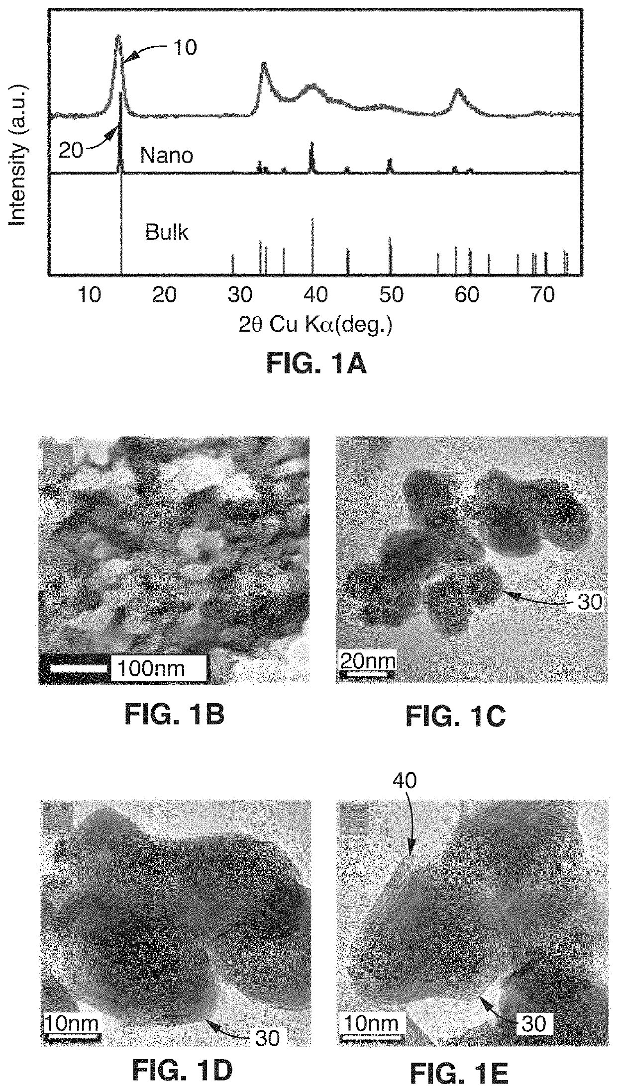
[0073]This disclosure describes the synthesis of highly defected nanocrystals with expanded atomic spacing and their use in high rate energy applications. For purposes of this disclosure, the term “nano” means less than about 100 nm. The term “highly defected” as used in this disclosure means that the layer spacing is larger than the spacing in perfect crystals. In addition, highly defected crystals according to this disclosure preferably have “frayed ends” which provide access to the interlayer crystals of the same material (e.g., access to the edges of the layer). In other words, some layers just stop and the edges have pores which give rise to the frayed ends. Increased surface area at least in part leads to a pseudocapacitive charge storage mechanism.

[0074]In one embodiment, the technology comprises synthetic metal dichalcogenides having a highly defected nanocrystalline layered structure, wherein layer spacing is larger than in perfect crystals of the same mate...


PUM

PropertyMeasurementUnit
voltageaaaaaaaaaa
particle sizeaaaaaaaaaa
charge storageaaaaaaaaaa

Abstract

A synthetic metal dichalcogenide having a highly defected nanocrystalline layered structure, wherein layer spacing is larger than in perfect crystals of the same material, wherein the defected structure provides access to interlayer crystals of the same material, and wherein the defected structure facilitates a pseudocapacitive charge storage mechanism. The metal dichalcogenide is receptive to intercalation of ions such as Li ions, Na ions, Mg ions, and Ca ions, and does not undergo a phase transition upon intercalation of Li ions, Na ions, Mg ions, or Ca ions. The metal dichalcogenide can be used, for example, as a component of an electrode that also includes a carbon derivative, and a binder, which are intermixed to form the electrode. The resultant composite electrode is highly porous and highly electronically conductive, and is suitable for use in devices such as symmetric capacitors, asymmetric capacitors, rocking chair batteries, and other devices.

Description

CROSS-REFERENCE TO RELATED APPLICATIONS[0001]This application claims priority to, and the benefit of, U.S. provisional patent application Ser. No. 62 / 259,144 filed on Nov. 24, 2015, incorporated herein by reference in its entirety.STATEMENT REGARDING FEDERALLY SPONSORED RESEARCH OR DEVELOPMENT[0002]This invention was made with Government support under DE-SC0001342 and under DE-SC0014213, awarded by the United States Department of Energy, and under DGE-0903720, awarded by the National Science Foundation. The Government has certain rights in the invention.INCORPORATION-BY-REFERENCE OF COMPUTER PROGRAM APPENDIX[0003]Not ApplicableNOTICE OF MATERIAL SUBJECT TO COPYRIGHT PROTECTION[0004]A portion of the material in this patent document may be subject to copyright protection under the copyright laws of the United States and of other countries. The owner of the copyright rights has no objection to the facsimile reproduction by anyone of the patent document or the patent disclosure, as it a...

Claims


Application Information

Patent Timeline
Patent Type & Authority Patents(United States)
IPC IPC(8): H01M4/58H01G11/38H01G11/58H01G11/40H01M10/054H01G11/50H01M10/052H01M4/136H01M4/62H01G11/06
CPCH01G11/58H01M4/625H01G11/06H01M10/054H01G11/40H01G11/38H01M4/622H01G11/50H01M4/5815H01M4/136H01M10/052Y02E60/10
Inventor TOLBERT, SARAH H.DUNN, BRUCE S.COOK, JOHNKIM, HYUNGSEOKLIN, TERRI CHAI
Owner RGT UNIV OF CALIFORNIA
Why Eureka
Try Eureka