
Twisted wire conductor for insulated electrical wire, insulated electrical wire, cord and cable

a technology of twisted wire and insulated electrical wire, which is applied in the direction of insulated conductors, cables, cables, etc., can solve the problems of inferior bending fatigue resistance, low strength of materials, and number of repetitions required, and achieve excellent bending fatigue resistance, high strength, and high electrical conductivity.

Active Publication Date: 2021-01-26
FURUKAWA ELECTRIC CO LTD
View PDF10 Cites 2 Cited by
  • Summary
  • Abstract
  • Description
  • Claims
  • Application Information

AI Technical Summary

Benefits of technology

The present invention provides a twisted wire conductor for an insulated electrical wire. The first conductor is made of a specific aluminum alloy with high strength and bending fatigue resistance, while the second conductor is made of a metal or alloy with higher electrical conductivity. This creates a twisted wire conductor that is both strong and has excellent bending fatigue resistance. The twisted wire conductor is also lighter than traditional copper or aluminum materials. The invention also includes an insulated electrical wire, a cord, and a cable that utilize this twisted wire conductor.

Problems solved by technology

However, pure aluminum materials have problems that the materials have low strength compared to copper-based materials, and that the number of repetitions required until breakage in a bending fatigue test is small, while the bending fatigue resistance is also inferior.
Furthermore, aluminum alloy materials of 2000 series (Al—Cu-based) and 7000 series (Al—Zn—Mg-based), which are aluminum-based alloy materials having relatively high bending fatigue resistance, have problems such as inferior corrosion resistance and stress corrosion cracking resistance and low electrical conductivity.
The aluminum conductor steel reinforced (ACSR) described in Non-Patent Document 1 is configured such that high tensile load (high tensile strength) is achieved by the steel core (steel wire) positioned at the center, and low electrical resistance (high electrical conductivity) is achieved by the hard aluminum wires disposed around the steel wire; however, the steel wire has low electrical conductivity compared to the copper wire, and weight reduction cannot be attempted.
In addition, since the hard aluminum wires, which are conventional aluminum alloy wires, disposed around the steel wire have low strength compared to copper alloy wires, the hard aluminum wires cannot be used for cables on which a force for pulling or bending acts repeatedly, as in the case of movable cables such as cabtire cables and elevator cables, and for cables that are exposed to high-cycle deformation at a low strain amount caused by vibration, as in the cases of restraining cables such as high-voltage cables for vehicles.
However, it is an object of Patent Document 1 to suppress the deterioration of bending characteristics, and no investigation has been conducted on securing strength and electrical conductivity to an extent equal to those of copper alloy materials that are used for twisted wire conductors, while also attempting weight reduction.
However, although the copper-coated aluminum alloy wire described in Patent Document 2 has slightly higher electrical conductivity than the electrical conductivity of pure aluminum wire, since the difference in the coefficient of thermal expansion between aluminum and copper is large, in a case in which the copper-coated aluminum alloy wire is subjected to a thermal history (heat cycle) of heat generation and cooling by, for example, repeatedly performing continuous conduction for long time period at a high current density or intermittent conduction, cracks are likely to be generated at the interface between the aluminum alloy wire and the copper coating.
Furthermore, when cracks propagate, the copper coating is detached from the aluminum alloy wire, and as a result, there is a problem that the electrical conductivity is decreased, and stable performance cannot be obtained.

Method used


Image

  • Twisted wire conductor for insulated electrical wire, insulated electrical wire, cord and cable
  • Twisted wire conductor for insulated electrical wire, insulated electrical wire, cord and cable
  • Twisted wire conductor for insulated electrical wire, insulated electrical wire, cord and cable

Examples


examples

[0127]Next, in order to further clarify the effects of the present invention, Examples and Comparative Examples will be described; however, the present invention is not intended to be limited to these Examples.

examples 1-1 to 1-30

[0128]First, each of rod materials having a diameter of 10 mmϕ and having the alloy compositions indicated in Table 1 was prepared, and the initial wire diameter was adjusted using each of the rod materials so as to satisfy (the working ratio of) the production conditions and the final element wire diameters described in Table 1. That is, first conductors (specific aluminum alloy wire material) having the wire diameters indicated in Table 1 were produced by adjusting the diameters by die drawing, swaging, rolling, and the like, and then performing annealing. Furthermore, second conductors were produced, according to conventional methods, as various wire materials having the same wire diameters as the first conductors indicated in Table 1 using any metal or alloy selected from the group consisting of copper, copper alloy, aluminum, and aluminum alloy. Then, twisted wire conductors having the twist structure as indicated in Table 1 were produced by twisting together the first conducto...

example 1-1

Conventional Example 1-1

[0138]Conventional Example 1-1 is an example of producing a twisted wire conductor having the same twist structure as that of Example 1-1, except that the twisted wire conductor was constructed only of second conductors formed from a pure copper material (tough pitch copper), without using the first conductor. At this time, the total cross-sectional area S1 of the first conductors was 0% of the nominal cross-sectional area S of the twisted wire conductor.


PUM

PropertyMeasurementUnit
temperatureaaaaaaaaaa
electric currentaaaaaaaaaa
diameteraaaaaaaaaa

Abstract

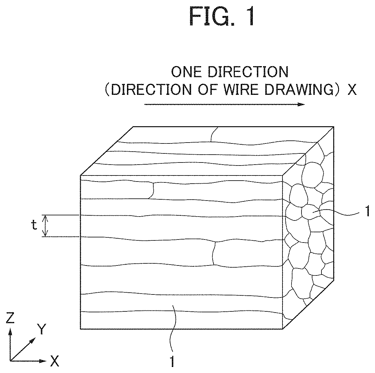
This twisted wire conductor 10 for an insulated electrical wire is configured so as to be in a mixed state in which a first conductor 20 and a second conductor 40 are twisted together. The first conductor comprises a specific aluminum alloy: which has an alloy composition that contains, by mass %, 0.2-1.8% of Mg, 0.2-2.0% of Si, 0.01-0.33% of Fe and a total of 0.00-2.00% of one or more elements selected from the group consisting of Cu, Ag, Zn, Ni, Co, Au, Mn, Cr, V, Zr, Ti and Sn, with the remainder comprising Al and unavoidable impurities; which has a fibrous metal structure in which crystal grains extend in one direction; and in which the average value of a dimension t which is perpendicular to the longitudinal direction of crystal grains is 400 nm or less in a cross section parallel to this one direction. The second conductor has a higher electrical conductivity than the first conductor 20 and comprises a metal or alloy selected from the group consisting of copper, copper alloys, aluminum and aluminum alloys. The twisted wire conductor exhibits high electrical conductivity, high strength and excellent bending fatigue resistance, and enables a reduction in weight.

Description

TECHNICAL FIELD[0001]The present invention relates to a twisted wire conductor for an insulated electrical wire, an insulated electrical wire, a cord, and a cable.BACKGROUND ART[0002]Conventionally, copper-based conductor materials have been widely used for cables that transmit electric power or signals, which are called cabtire cables such as robot cables, elevator cables, and high voltage cables for vehicles. Among such cables, movable cables are configured to be capable of migrating (moving), and since it is assumed that in a conventional use mode, a force for pulling or bending concomitantly with migration acts repeatedly, it is desirable that movable cables have not only the characteristics for transmitting electric power or the like but also high tensile strength, and further have excellent characteristics for enduring repeated bending deformation, so-called bending fatigue resistance. Furthermore, regarding restraining cables such as high voltage cables for vehicles (electric...

Claims


Application Information

Patent Timeline
Patent Type & Authority Patents(United States)
IPC IPC(8): H01B11/02H01B1/02C22C21/02C22C21/06C22C21/12H01B7/00C22C9/00H01B5/08H01B7/04C22F1/05
CPCH01B1/02C22C9/00C22C21/02C22C21/06C22C21/12C22F1/05H01B5/08H01B7/0009H01B7/04C22C21/08C22C21/14C22C21/16C22F1/043H01B1/023
Inventor KANEKO, HIROSHI
Owner FURUKAWA ELECTRIC CO LTD
Learn More