Honeycomb filter

a filter and honeycomb technology, applied in the field of honeycomb filters, can solve the problems of increasing the pressure loss of the honeycomb filter, and achieve the effects of low pressure loss, increased pores total volume, and large thickness

Active Publication Date: 2021-07-13
NGK INSULATORS LTD
View PDF18 Cites 6 Cited by
  • Summary
  • Abstract
  • Description
  • Claims
  • Application Information

AI Technical Summary

Benefits of technology

[0032]A honeycomb filter of the present invention is configured to include a first partition wall disposed between an inflow cell and an outflow cell and having thickness T1 and a second partition wall disposed between inflow cells and having thickness T2, and T1 is smaller than T2. That is, the honeycomb filter of the present invention satisfies the relationship of “T2>T1”. With this configuration, the honeycomb filter of the present invention can have an advantageous effect of having low pressure loss as compared with an existing honeycomb filter having the same open frontal area while maintaining the isostatic strength equal to such an existing honeycomb filter.
[0033]That is, such a second partition wall having relatively large thickness T2 can increase the total volume of pores in the second partition wall relatively, and therefore exhaust gas can easily flow through the pores of the second partition wall. This allows exhaust gas flowing into the inflow cells to easily flow to the outflow cells via the pores of the second partition wall, even when PMs, such as soot, are accumulated on the surface of the first partition wall and so the first partition wall has increased permeation resistance. Thereby the honeycomb filter can have low pressure loss. Especially exhaust gas flowing from inflow cells to outflow cells mainly passes through the first partition wall, and so PMs, such as soot, are easily accumulated on the first partition wall. As PMs are accumulated, the permeation resistance easily increases at the first partition wall. According to the honeycomb filter of the present invention, when the permeation resistance increases at the first partition wall, the second partition wall can function as the through channel of exhaust gas very effectively.
[0034]Note here that contribution to an increase in pressure loss at the initial state of the operation is lower at the second partition wall than at the first partition wall. This means that a honeycomb filter including such a second partition wall having relatively large thickness T2 can suppress an increase in pressure loss at the initial state of the operation. Such a honeycomb filter including a second partition wall having relatively large thickness T2 can increase the heat capacity of the honeycomb filter as a whole and so the improved thermal shock resistance also can be expected.

Problems solved by technology

A honeycomb filter as described in Patent Document 5 therefore may have a problem of non-uniform flow of exhaust gas between these two types of partition walls, and so of an increase in pressure loss of the honeycomb filter.

Method used


Image

  • Honeycomb filter
  • Honeycomb filter
  • Honeycomb filter

Examples


example 1

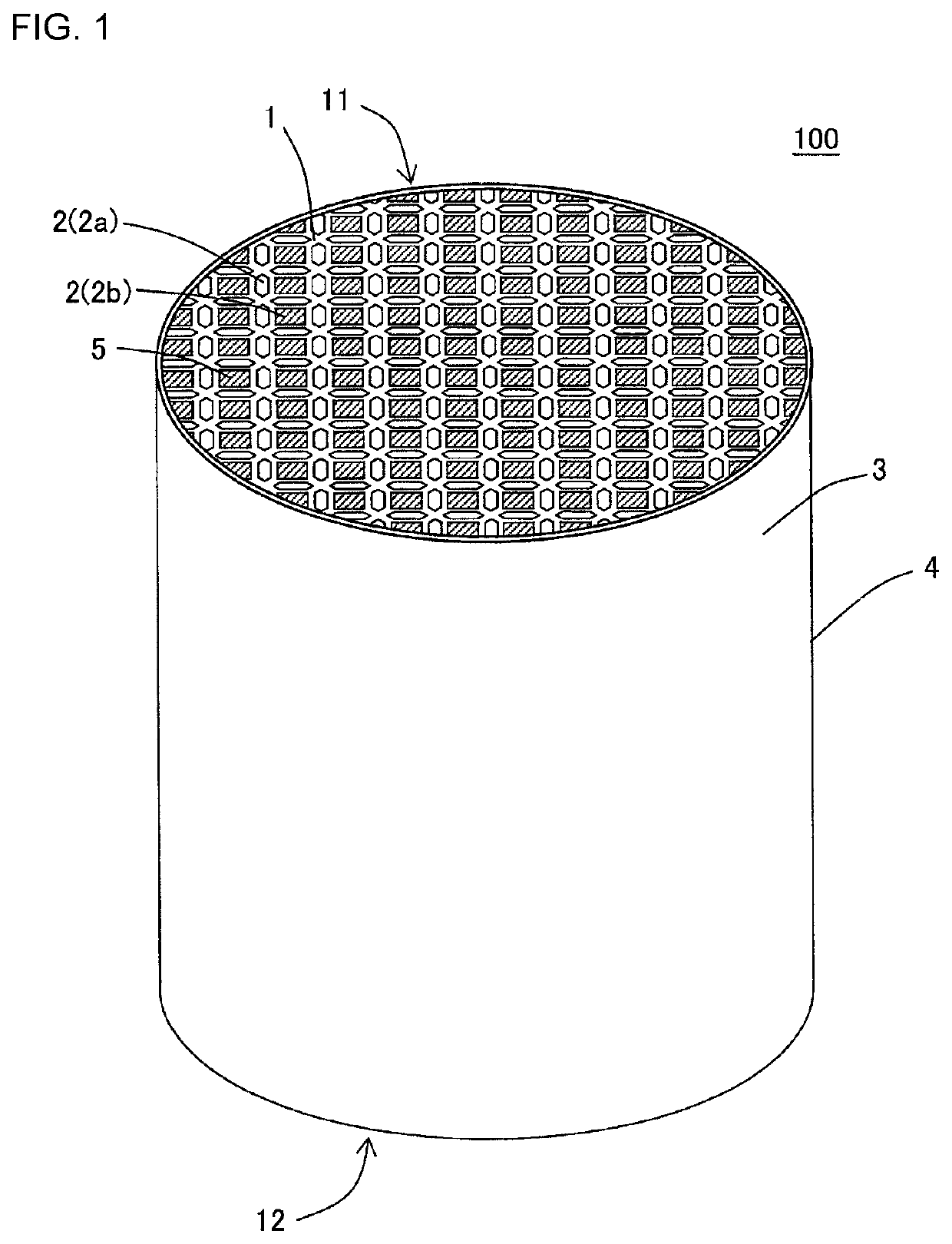
[0087]Firstly a kneaded material was prepared to produce a honeycomb substrate. In Example 1, for the raw material powder to prepare a kneaded material, silicon carbide (SiC) powder and metal silicon (Si) powder were mixed at the mass ratio of 80:20 to prepare a mixture powder. To the mixture powder, binder, a pore former and water were added to have a forming raw material. Next, the forming raw material was kneaded to have a round pillar-shaped kneaded material.

[0088]Next, the kneaded material was extruded using a die for manufacturing of a honeycomb formed body to have a honeycomb formed body having a round pillar shape as the overall shape.

[0089]Next, the honeycomb formed body was dried by a microwave dryer, and then was dried completely by a hot-air drier, and then both end faces of the honeycomb formed body were cut so as to have predetermined dimensions.

[0090]Next, a plugging portion was formed to the dried honeycomb formed body. Specifically a mask was firstly applied to the ...

examples 2 to 30

[0102]Honeycomb filters of these Examples were manufactured similarly to Example 1 other than that “thickness T1 of the first partition wall (μm)”, “thickness T2 of the second partition wall (μm)” and “T2 / T1” were changed as shown in Table 1. For the honeycomb filters of Examples 2 to 30, the “pressure loss” and “thermal shock resistance” were evaluated by the method similar to Example 1. Table 1 shows the result.

examples 31 to 60

[0104]In Examples 31 to 60, the amount of pore former was increased during the preparation of a kneaded material to manufacture a honeycomb substrate as compared with the kneaded material prepared in Example 1, so as to manufacture a honeycomb filter including the partition wall having the porosity of 41%. Honeycomb filters of these Examples were manufactured similarly to Example 1 other than that “thickness T1 of the first partition wall (μm)”, “thickness T2 of the second partition wall (μm)” and “T2 / T1” were changed as shown in Table 2 by using such a kneaded material. For the honeycomb filters of Examples 31 to 60, the “pressure loss” and “thermal shock resistance” were evaluated by the method similar to Example 1. Table 2 shows the result. In Examples 31 to 60, Comparative Example 2 described below was used as their reference honeycomb filter.


PUM

PropertyMeasurementUnit
thickness T1aaaaaaaaaa
lengthaaaaaaaaaa
porosityaaaaaaaaaa

Abstract

Provided is a honeycomb filter, including: a pillar-shaped honeycomb substrate having an inflow end face and an outflow end face and including a porous partition wall surrounding a plurality of cells; and a plugging portion disposed at any one of ends of the cells at the inflow end face and at the outflow end face. In a cross section orthogonal to an extending direction of the cells, inflow cells have a pentagonal or a hexagonal shape, and outflow cells have a square shape. The cells are configured that the inflow cells surround one outflow cell and one side of an inflow cell and one side of an adjacent outflow cell are parallel to each other. The partition wall is configured that thickness of a first partition wall disposed between the inflow cells and the outflow cells is smaller than thickness of a second partition wall disposed between the inflow cells.

Description

[0001]“The present application is an application based on JP-2017-068047 filed on Mar. 30, 2017 with Japan Patent Office, the entire contents of which are incorporated herein by reference.”BACKGROUND OF THE INVENTIONField of the Invention[0002]The present invention relates to honeycomb filters. More specifically the present invention relates to a honeycomb filter having low pressure loss while maintaining the isostatic strength.Description of the Related Art[0003]Internal combustion engines are used as a power source in various industries. Exhaust gas emitted from such an internal combustion engine during burning of the fuel, however, contains particulate matters, such as soot and ash, together with toxic gas, such as nitrogen oxides. Hereinafter the particulate matters may be called “PMs”. “PM” stands for “Particulate Matter”. Regulations on the removal of PMs emitted from a diesel engine are becoming stricter worldwide. A honeycomb-structured wall flow type filter, for example, ha...

Claims


Application Information

Patent Timeline
Patent Type & Authority Patents(United States)
IPC IPC(8): B01D46/24F01N3/022F01N3/035
CPCB01D46/2474B01D46/247B01D2046/2433B01D2046/2481B01D2046/2492B01D2046/2496F01N3/0222F01N3/035B01D46/2486B01D46/2492B01D46/249B01D46/2482B01D46/2476B01D46/24491B01D46/2498B01D46/2429
Inventor YASUI, OSAMUAOKI, TAKASHIMIURA, KAZUTOIIDA, TOMOHIROMIYAIRI, YUKIO
Owner NGK INSULATORS LTD
Why Eureka
Try Eureka