Ion source for analysis of low volatility species in the gas phase

a low volatility, gas phase technology, applied in the direction of spectrometer detectors, particle separator tube details, instruments, etc., can solve the problems of insufficient detection accuracy of inability to handle and accurately detect them in breath, and inability to detect larger molecules with lower volatilities with state-of-the-art technologies. , to achieve the effect of stabilizing the flow configuration, reducing memory effects and background levels, and reducing condensation of low volatility

Active Publication Date: 2021-07-27
FOSSIL ION TECH
View PDF13 Cites 3 Cited by
  • Summary
  • Abstract
  • Description
  • Claims
  • Application Information

AI Technical Summary

Benefits of technology

[0044]The new ionizer comprises a flow deflector (126) arranged between said source of charging ions (102) and the inlet of said analyzer (103) and having an orifice (105) aligned with said inlet of said analyzer (103). A flow of clean gas (109) is introduced in the space defined between said flow deflector (126) and the inlet of said analyzer (103) through a clean gas inlet (106). Said flow deflector (126) accelerates said clean (109) gas towards said inlet of said analyzer (103), and the flow of clean gas is detached from said flow deflector at the edge of said orifice (105). This produces an interface surface in said orifice (105) between said clean gas (109) and said flow of sample gas (111). The streamlines (124) of the clean gas (109) flow collapse at the axis of said orifice (105) and turn towards the inlet of the analyzer (103), where the flow is quickly accelerated towards the analyzer. As a result, no net clean gas (109) is introduced in the ionization chamber (113), and turbulent structures are not introduced into the ionization chamber (113). This configuration minimizes the contamination that enters into the analyzer, and minimizes the dilution of the sample flow (111) due to turbulent mixing with the clean gas (109). In addition, the clean gas (109) focuses the ions towards the inlet of the analyzer (103), thus improving the transmission of ions. The new configuration improves the ionization efficiency by minimizing dilution of neutral sample molecules in the ionization region (107), and by optimizing the flow of ions that are transferred towards the inlet of the analyzer (103). In contrast with its predecessors, the new ionizer does not require extra electrodes to operate. This reduces the surface area of the inner walls (123) of the ionizer, eliminates the stagnated regions produced by the extra electrodes, in which contamination tends to build up, and thus reduces memory effects and background signals. This is particularly important to improve the background levels for low volatility species, which tend to condensate in the inner walls (123) of the system.
[0045]When the source of charging ions (102) produces ions moving in a predominant direction, the interaction between said charging ions and the surrounding gas induces the formation of a toroidal vortex (125). Even with a stable configuration, the flow induced by this toroidal vortex (125) can carry the clean gas into the ionization region (114), excluding the sample flow (111) from it, and thus reducing ionization efficiency. Another embodiment of the present invention incorporates groove (134) carved in the side of the flow deflector (126) that is facing the ionization chamber (113). The size of this groove (134) matches the size of said toroidal vortex (125) to lock said vortex (125) in a fixed position. In addition to it, in another embodiment of the present invention, a corner (135) with high curvature is used to induce the detachment of said vortex (125) at a fixed and controlled position. By introducing the sample flow through an opening (138) located above said groove (134) or said corner (135), the toroidal vortex (125) of the present invention sucks the sample flow (111) towards the ionization region (114), thus improving its ionization efficiency.
[0046]The toroidal vortex (125) induced by the movement of the charging ions can destabilize the interface between said clean gas (111) and said sample gas (109), causing turbulent mixing and poor ionization efficiency. This is because, in this interface (117), the flow induced by said toroidal vortex (125) flows radially and away from the axis, while the clean gas (109) flows in the opposite direction (radially and towards the axis). In one embodiment of the present invention, the edge of said orifice (105) is blunt, forming a blunt edge (127). As a result, when the clean gas (109) is detached in the blunt edge (127), it produces a second toroidal vortex (128), located in said blunt edge (127). The side of the second toroidal vortex (127) facing the clean gas (109) moves in the same direction as the clean gas (109), and the side of the second toroidal vortex (127) facing the toroidal vortex (125) induced by the movement of the ions also moves in the same direction as the flow induced by this toroidal vortex (125). This reduces the shear stress, improves the stability of the configuration, and thus improves the ionization efficiency.
[0049]In another embodiment of the present invention, a coaxial inlet (152) and a coaxial outlet (150) of cooling gas (151) form a capsid (149) of cooling gas that is used to cool the source of charging ions (102) and to isolate it from the sample gas (111). Dilution of the sample gas due to the cooling gas (151) is minimized because the cooling gas flows radially and towards the axis, in the same direction as the toroidal vortex, and this helps to stabilize the flow configuration. When the source of charging ions (102) is an electrospray, this enables for the sample gas (111) and the ionization region (114) in front of the source of charging ions to operate at temperatures above the boiling point of the electrospray, while the source of charging ions (102) remains at a lower temperature. As a result, condensation of low volatility species is reduced, and memory effects and background levels are also reduced, thus improving the Limits of Detection for low volatility species.
[0050]Another embodiment of the present invention incorporates a secondary inlet (154) to introduce a flow of liquid at said inlet of sample gas (112). This allows for the humidity of the sample gas to be increased to a point for which humidity variations do not change the ionization efficiency. This also allows for the introduction of cleaning solutions when no sample gas is being introduced.

Problems solved by technology

However, larger molecules are not used because handling and accurately detecting them in breath is technically very challenging.
For an analyzer of molecules to provide biologically relevant information, it is of paramount importance to be able to detect larger molecules, but larger molecules with lower volatilities cannot be detected with sufficient accuracy with state of the art technologies.
At the cost of introducing a new and time-consuming step, pre-concentration techniques such as Solid-Phase Micro-Extraction (SPME) increase the sensitivity of the GC-MS analysis.
However, these methods require long analysis times, which are not compatible with real-time analysis, and their sensitivity is limited by the fact that the GC column can only accept a very small amount of sample.
For a human, it is well known that drastic changes can occur in a matter of minutes.
When a complex sample is analyzed, this produces fragments at virtually all masses, which produce a high background signal level that deteriorates the limits of detection.
While this approach provided a very good sensitivity, the vapors were also introduced in the vacuum side of the mass spectrometer, which was rapidly contaminated.
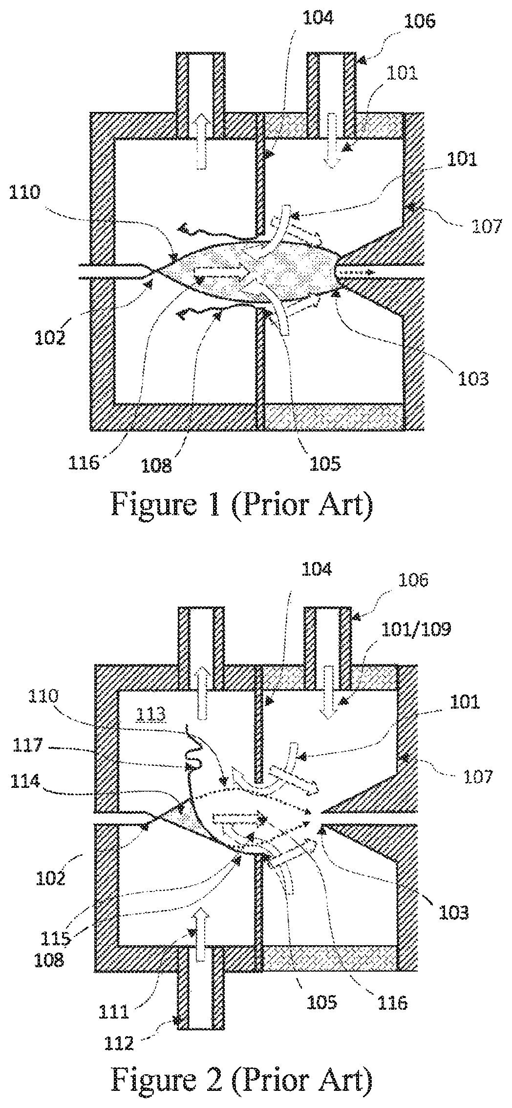
However, its ionization efficiency, which is defined as the ratio of sample ions transferred to the analyzer over sample molecules introduced ion the ionizer, was limited by two main factors: on the one hand, the shear layer (117), which separates the counterflowing clean gas (109) and the sample gas (111), is unstable.
Further theoretical and experimental studies showed that, when the sample included reactive vapors that compete for the available electrical charge, charge competition effects reduce the p ratio, thus reducing the ionization efficiency [9].
While the ionization efficiency improvement can be viewed as an advantage, this is very problematic because the fact that ionization efficiency can change during an analysis due to humidity variations hinders quantitative analysis.
In particular, biological samples such as breath, or cell culture headspace, very often carry water vapors, which can change the ionization efficiency of the sample molecules unpredictably.
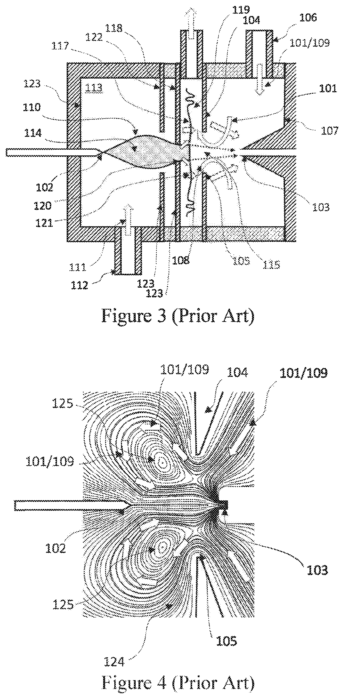
However, this configuration creates a new problem: the system is more susceptible to contamination, which condensates on the inner walls (123) of the ionizer.
This produces high background signals, which deteriorate the LoD.
This is produced by the following reasons: (i) the complexity of the internal geometry of the system is dramatically increased as a result of adding the electrodes.
As a result, accessing the internal parts of the ionizer is difficult, and cleaning and maintenance procedures become very time consuming.
(iii) In addition, the intricate geometry leads to stagnated regions in which contamination tends to build up.
However, the temperature of operation of the SESI described in U.S. Publication No. 2010 / 0264304 A1, and the SESI described in U.S. Pat. No. 8,217,342 B2 and U.S. Pat. No. 8,461,523 B2, is limited by the boiling point of the electrospray liquid because the electrospray cannot be formed if the liquid boils.
However, at this temperature, the evaporation of liquid at the Taylor cone meniscus of the spray is quite substantial.
Since the different ingredients of the electrospray liquid have different evaporation ratios, the composition of the liquid at the very tip of the cone varies in an uncontrolled fashion.
This reduces the predictability of the electrospray conditions, thereby affecting the predictability of the ionization efficiency.
This is particularly problematic because small convection changes, temperature variations, or even humidity variations, affect the composition of the liquid arriving at the tip of the meniscus when the temperature of the ionizer approaches the boiling point of the liquid.
This results in a signal variability that hinders the quantitative determination of the measured species.
On top of this, since the boiling point of the electrospray liquid is below the boiling and / or sublimation point of most of the low volatility species of interest, the temperatures that can be achieved with these configurations are not sufficient to ensure that the analytes of interest do not condensate onto the inner walls (123) of the ionizer.
As a result, low volatility species tend to condensate and be desorbed onto the inner walls of the ionizer, thus increasing the background levels.
While these solvents enable an increase in the temperature of operation of the ionizer, they are usually not compatible with the mass spectrometer.
The vapor pressure of these liquids is high enough to deteriorate the mass spectrometer performance, but not enough for the vacuum pump system to eliminate them efficiently.
This configuration solves the compatibility problem between the high-temperature SESI and the MS, but it is limited only to the case in which a DMA is interposed between the SESI and the MS.
In conclusion, previous SESI configurations show promising results, but they are subjected to the following problems:(i) previous attempts to improve the ionization efficiency are prone to contamination over time.
This results in high signal background levels, which deteriorate the Limits of Detection of the instrument;(ii) the temperature of operation in the ionization region is limited by the boiling point of the electrospray liquid, which is limited by the type of analyzer connected downstream of the SESI.
When the SESI is coupled directly with a mass spectrometer, this limits the maximum operating temperature of the system.
As a result, low volatility species tend to condensate in the inner walls of the ionizer, thereby increasing background signals and deteriorating LoD;(iii) since the temperature in the ionization chamber is very close to the boiling point of the electrospray liquid, evaporation of the electrospray liquid in the tip of the spray is quite substantial.
This affects the stability and the repeatability of the electrospray.
As a result, the signals become unstable, lowering the quality of the measurements.(iv) humidity content and charge competition effects affect the ionization efficiency, which depends on the particular configuration of the measurement, and which is not always constant and predictable.
As a result, establishing a direct correlation between the signal intensity produced by an analyte, and its concentration in the sample gas is not always possible.
This hinders quantitative analysis.
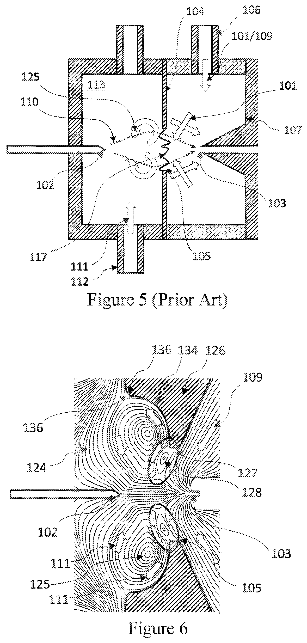
The ionization efficiency of the ionizers designed with this numerical simulation method falls dramatically when the sample flow is below 0.5 lpm, but the simulations failed to predict this.
This mismatch between simulated results and empirical results indicated that a new numerical method was required to better understand the fluid mechanics within the SESI.

Method used


Image

  • Ion source for analysis of low volatility species in the gas phase
  • Ion source for analysis of low volatility species in the gas phase
  • Ion source for analysis of low volatility species in the gas phase

Examples


Embodiment Construction

[0066]On the Interaction Between the Toroidal Vortex and the Clean Gas:

[0067]On the one hand, in the present invention, the clean (109) gas must flow radially towards the inlet (103) of the analyzer to focus and drive the sample ions to the analyzer. On the other hand, the part of the toroidal vortex (125) that is most downstream of the electrospray (102), and hence nearest the clean gas (109), flows radially and away from the central axis. If the clean gas (109) is introduced at low velocity, as in the simulation of FIG. 4, the toroidal vortex (125), sucks the clean gas (109) into the ionization chamber (113), thus preventing the sample flow from being ionized. If the clean gas (109) is introduced with a higher velocity, then the flow configuration becomes unstable, and our numerical method can not cope with turbulence. For this reason, FIG. 5 illustrates this configuration schematically. In the interface (117) between the clean gas (109) and the toroidal vortex (125), the two stre...


PUM

PropertyMeasurementUnit
time resolutionaaaaaaaaaa
body temperatureaaaaaaaaaa
atmospheric pressureaaaaaaaaaa

Abstract

A method and apparatus that ionize vapors for their chemical analysis is described. The new ionizer improves the ionization efficiency by reducing dilution of sample molecules and improving transmission of ions to the analyzer. This is accomplished by a new flow configuration, in which a stream of clean gas focuses the ions towards the analyzer. A deflector prevents the formation of turbulent perturbation, and the ionization maintains a laminar regime without the need for additional separating walls or electrodes. The flow within the ionizer is configured so that contaminants released by the inner walls of the ionizer do not reach the ionization region. The resulting ionizer improves the ionization efficiency, and the background levels for low volatility species. This makes it ideal for the analysis of low volatility species in the gas phase. One application of this ionizer is the analysis of human breath in real time.

Description

CROSS-REFERENCE TO RELATED APPLICATION[0001]This application is a National Stage Filing under 35 U.S.C. § 371 of PCT Application No. PCT / IB2017 / 057255, filed on Nov. 17, 2017, the entire contents of which are incorporated by reference herein.TECHNICAL FIELD OF THE INVENTION[0002]The present invention relates to an apparatus and a method to ionize molecules and aerosols in the gas phase for their analysis by an ion analyzer, including mass spectrometers, ion mobility spectrometers, and combinations of the two. In particular, the invention describes a new configuration that improves the ionization efficiency, the background levels, and the stability of the signals produced by molecules with low volatility. This improves the limits of detection and facilitates a quantitative correlation between the measured signals and the concentrations of the molecules in the gas. The new ionizer is particularly well suited for the analysis of breath in real-time.BACKGROUND ART OF THE INVENTION[0003]...

Claims


Application Information

Patent Timeline
Patent Type & Authority Patents(United States)
IPC IPC(8): H01J49/00H01J49/16G01N27/622H01J49/02H01J49/04H01J49/14
CPCH01J49/165G01N27/622H01J49/025H01J49/0422H01J49/145
Inventor VIDAL-DE-MIGUEL, GUILLERMO
Owner FOSSIL ION TECH
Why Eureka
Try Eureka