Compression capable annular frames for side delivery of transcatheter heart valve replacement

a transcatheter heart valve and annular frame technology, applied in the field of transcatheter heart valve replacement, can solve the problems of prone to fracture of the strut of the valve, inability to fully correct the valve problem, and placed in the descending aorta instead of the heart itself, and achieve the effect of facilitating rolling and folding

Active Publication Date: 2022-03-22
VDYNE INC
View PDF1212 Cites 2 Cited by
  • Summary
  • Abstract
  • Description
  • Claims
  • Application Information

AI Technical Summary

Benefits of technology

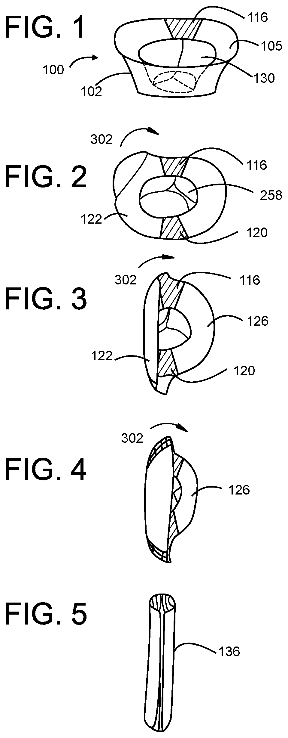
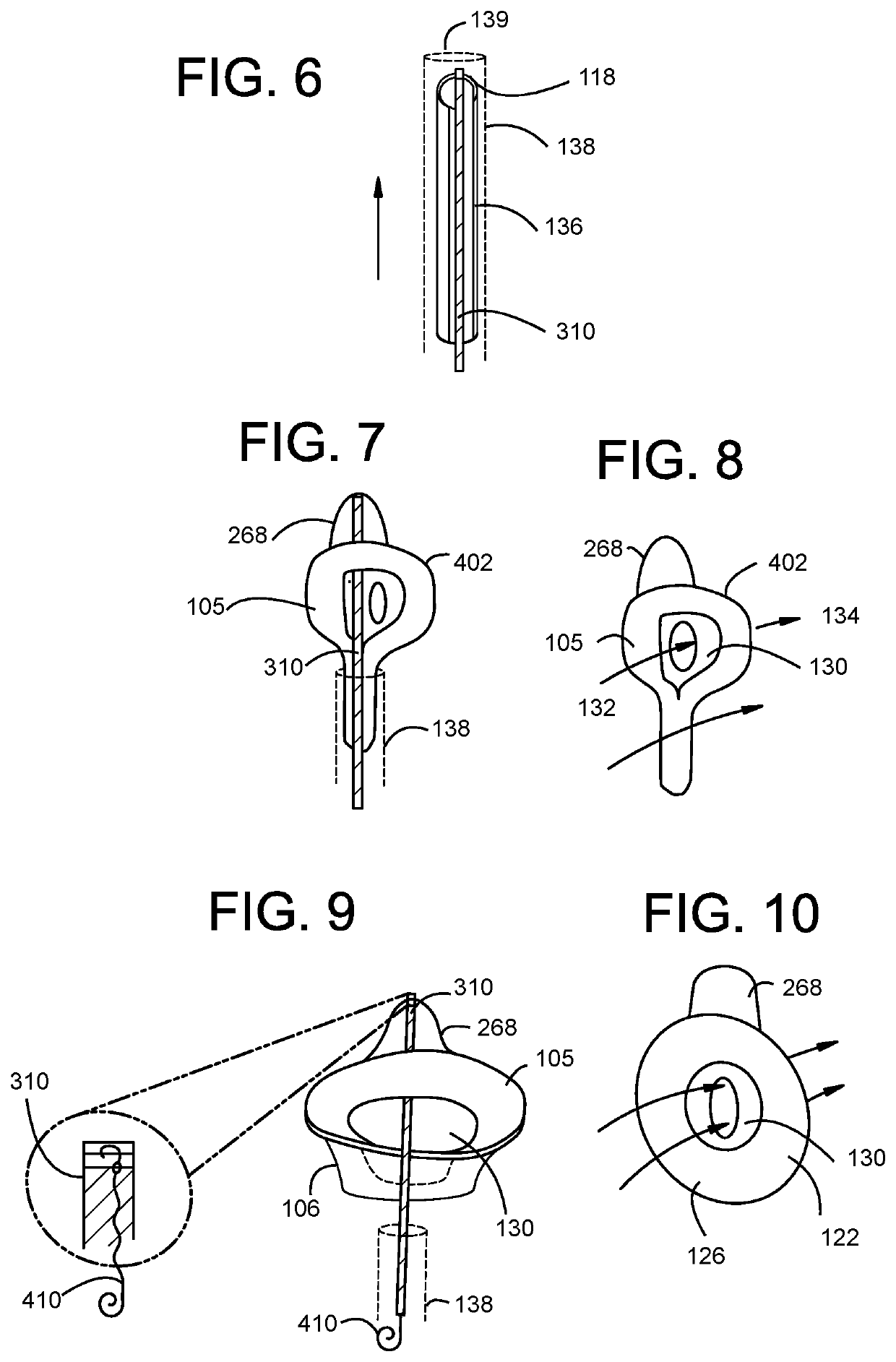
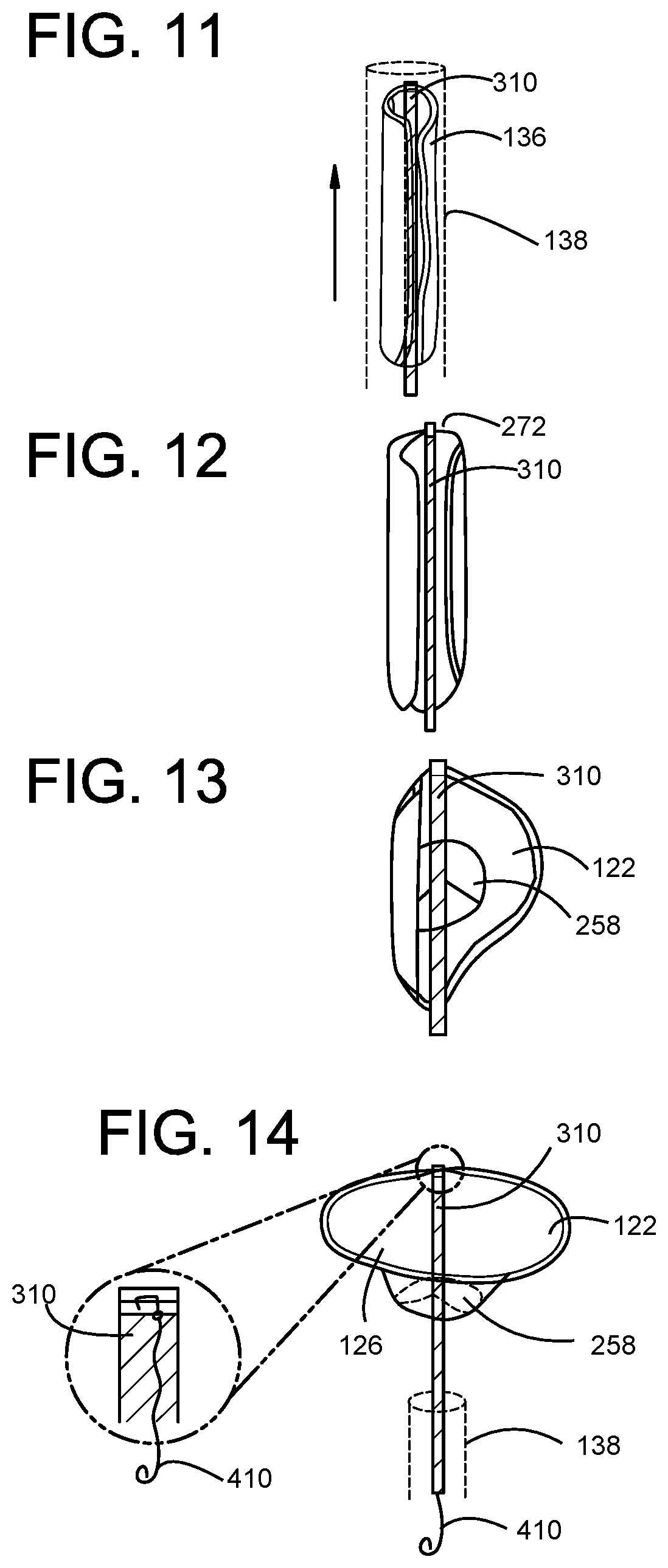
[0009]The present invention is directed to methods and devices related to a transcatheter heart valve replacement (A61F2 / 2412), and in particular Compression Capable Annular Frames for a side (length-wise) delivered transcatheter prosthetic heart valve having a annular support frame having compressible wire cells that facilitate rolling and folding the valve length-wise, or orthogonal, to the central axis of the flow control component, allowing a very large diameter valve to be delivered and deployed from the inferior vena cava directly into the mitral or tricuspid valve, e.g. having a height of about 5-60 mm and a diameter of about 25-80 mm using a 24-36Fr delivery catheter, without requiring an oversized diameter catheter and without requiring delivery and deployment from a catheter at an acute angle of approach.
[0026]In another preferred embodiment, there is provided a side delivered transcatheter heart valve, wherein the annular support frame is comprised of a plurality of compressible wire cells having an orientation and cell geometry substantially orthogonal to the central vertical axis to minimize wire cell strain when the annular support frame is configured in a vertical compressed configuration, a rolled compressed configuration, or a folded compressed configuration.
[0048]In another preferred embodiment, there is provided a method for improving hemodynamic flow during implantation of a transcatheter prosthetic heart valve, comprising:advancing a delivery catheter to the desired location in the body and delivering the valve of claim 1 to the desired location in the body;partially releasing the valve from the delivery catheter to establish blood flow around the partially released valve and establish blood flow through the flow control component;completely releasing the valve from the delivery catheter while maintaining attachment to the valve with a positioning catheter or wire to transition to increased blood flow through the flow control component and decreasing blood flow around the valve; anddeploying the valve into a final mounted position to transition to complete blood flow through the flow control component and minimal or no blood flow around the valve, and disconnecting and withdrawing the positioning catheter or wire from the valve.
[0049]In another preferred embodiment, there is provided a method of improving hemodynamic flow, wherein the RVOT tab is in the RVOT during the transition from partial release of the valve to complete release of the valve.

Problems solved by technology

However, one downside of this design was that it could only be placed in the descending aorta instead of the heart itself.
For this reason it did not fully correct the valve problem, only alleviate the symptoms.
However, the struts of these valves tended to fracture from fatigue over time.
However, a downside of this design is that it allows some regurgitation.
Additionally, a problem with stent-style replacement valves is that they often continue to have the regurgitation or leakage problems of prior generations of valves, as well as require expensive materials engineering in order to cope with the 100's of millions of cycles encountered during just a few years of normal heart function.

Method used


Image

  • Compression capable annular frames for side delivery of transcatheter heart valve replacement
  • Compression capable annular frames for side delivery of transcatheter heart valve replacement
  • Compression capable annular frames for side delivery of transcatheter heart valve replacement

Examples


example

[0208]The transcatheter prosthetic heart valve may be percutaneously delivered using a transcatheter process via the femoral through the IVC, carotid, sub-xyphoid, intercostal access across the chest wall, and trans-septal to the mitral annulus through the fossa ovalis.

[0209]The device is delivered via catheter to the right or left atrium and is expanded from a compressed shape that fits with the internal diameter of the catheter lumen. The compressed valve is loaded external to the patient into the delivery catheter, and is then pushed out of the catheter when the capsule arrives to the atrium. The cardiac treatment technician visualizes this delivery using available imaging techniques such as fluoroscopy or ultrasound.

[0210]In a preferred embodiment the valve self-expands upon release from the catheter since it is constructed in part from shape-memory material, such as Nitinol®, a nickel-titanium alloy, or a cobalt-chromium alloy, alloys used in biomedical implants.

[0211]In anothe...

example — manufacturing process

Example—Manufacturing Process

[0213]In a preferred embodiment the invention includes a process for manufacturing a side delivered transcatheter prosthetic heart valve frame, comprising:

(i) using additive or subtractive metal or metal-alloy manufacturing to produce

a self-expanding annular support frame,

wherein the additive metal or metal-alloy manufacturing is 3D printing or direct metal laser sintering (powder melt), and

wherein the subtractive metal or metal-alloy manufacturing is photolithography, laser sintering / cutting, CNC machining, electrical discharge machining.

[0214]In another preferred embodiment, there is provided a process for manufacturing a side delivered transcatheter prosthetic heart valve frame, further comprising the steps of: (ii) mounting a flow control component within the valve frame, said flow control component configured to permit blood flow along the central vertical axis through an inflow end of the flow control component and block blood flow through an outfl...


PUM


Abstract

The invention relates to a transcatheter heart valve replacement (A61F2 / 2412), and in particular Compression Capable Annular Frames for a side delivered transcatheter prosthetic heart valve having a annular support frame having compressible wire cells that facilitate rolling and folding the valve length-wise, or orthogonally to the central axis of the flow control component, allowing a very large diameter valve to be delivered and deployed to the tricuspid valve from the inferior vena cava or superior vena cava, or trans-atrially to the mitral valve, the valve having a height of about 5-60 mm and a diameter of about 25-80 mm, without requiring an oversized diameter catheter and without requiring delivery and deployment from a catheter at an acute angle of approach.

Description

CROSS-REFERENCE TO RELATED APPLICATIONS[0001]This application claims priority to and the benefit of U.S. Provisional Patent Application Ser. No. 62 / 777,070, filed Dec. 8, 2018, entitled “Compression Capable Annular Frames for Side Delivery of Transcatheter Heart Valve Replacement,” the disclosure of which is incorporated herein by reference in its entirety.BACKGROUND OF THE INVENTIONField of the Invention[0002]The invention relates to a transcatheter heart valve replacement (A61F2 / 2412).Description of the Related Art[0003]In 1952 surgeons implanted the first mechanical heart valve. This first valve was a ball valve and it was designed by Dr. Charles Hufnagel. The recipient of this valve was a 30-year-old woman who could lead a normal life after the surgery. However, one downside of this design was that it could only be placed in the descending aorta instead of the heart itself. For this reason it did not fully correct the valve problem, only alleviate the symptoms. However it was a ...

Claims


Application Information

Patent Timeline
Patent Type & Authority Patents(United States)
IPC IPC(8): A61F2/95A61F2/24A61F2/92A61F2/91A61B17/00
CPCA61F2/95A61B17/00234A61F2/2418A61F2/2427A61F2/2436A61F2/91A61F2/92A61B2017/00243A61B2017/00292A61B2017/00305A61B2017/00323A61F2/9522A61F2210/0014A61F2220/0008A61F2240/001A61F2230/0095A61F2250/0039
Inventor CHRISTIANSON, MARKVIDLUND, ROBERTSAIKRISHNAN, NEELAKANTAN
Owner VDYNE INC
Why Eureka
Try Eureka