
Magnetic core for saturable reactor, magnetic amplifier type multi-output switching regulator and computer having magnetic amplifier type multi-output switching regulator

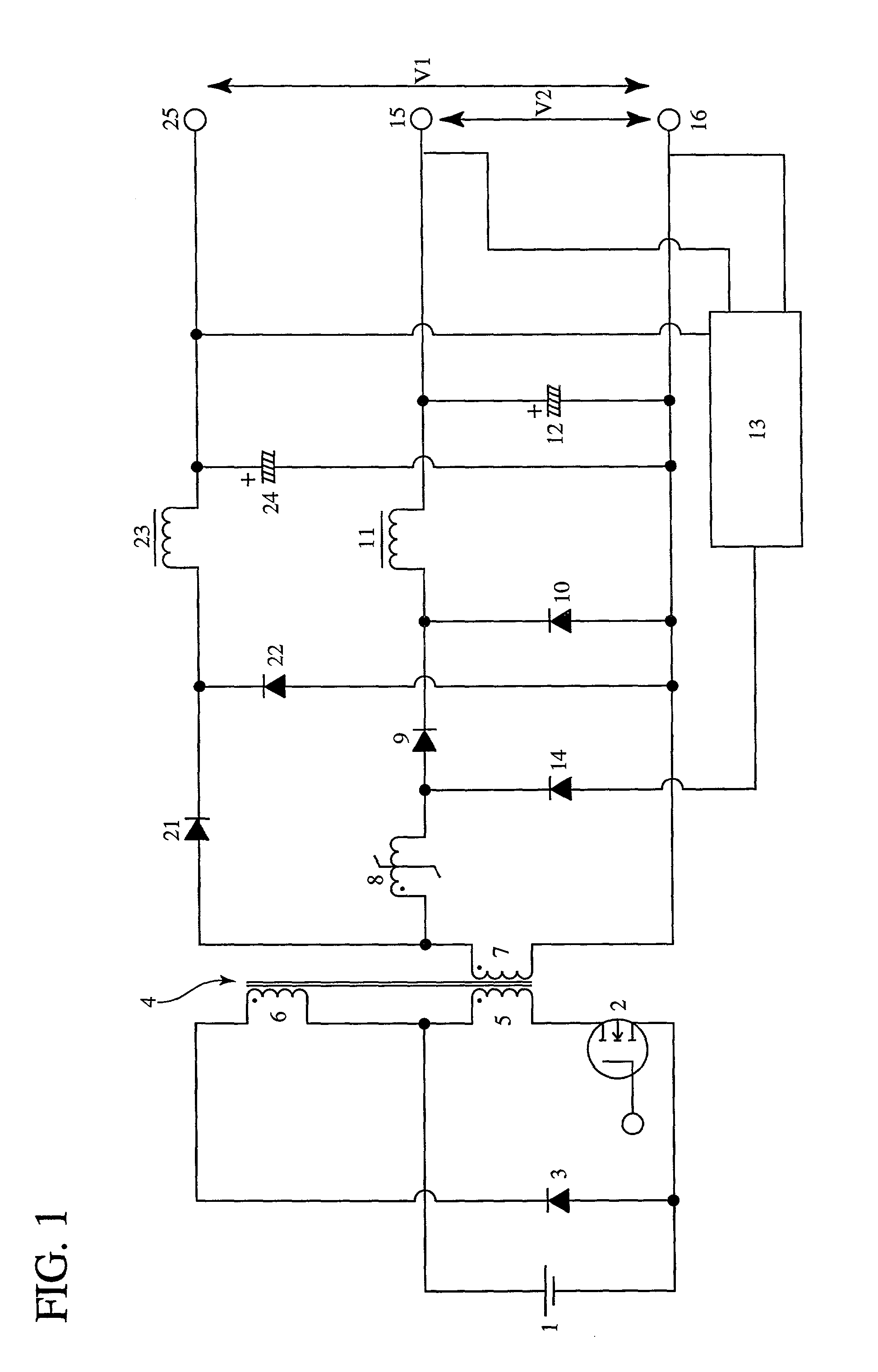
a saturable reactor and multi-output technology, applied in the direction of magnetic bodies, process and machine control, instruments, etc., can solve the problems of significant temperature rise of the saturable reactor, impracticality of using the anisotropic 50%-ni permalloy core at a switching frequency higher than 20 khz, and increase the number of anisotropic cores, etc., to achieve high reliability, reduce the number of circuit elements, and stable output

Inactive Publication Date: 2001-10-25
HITACHI METALS LTD
View PDF0 Cites 5 Cited by
  • Summary
  • Abstract
  • Description
  • Claims
  • Application Information

AI Technical Summary

Benefits of technology

The Fe-based alloy magnetic core minimizes voltage drops and temperature rise, enabling a compact, high-efficiency, and reliable multi-output switching regulator capable of operating at higher frequencies without additional circuit elements, maintaining stable output voltages even at large load currents.

Problems solved by technology

However, since the anisotropic 50%-Ni permalloy core shows a large core loss at a higher frequency range, the switching frequency is limited to about 20 kHz at most, and it has been recognized in the art that the use of the anisotropic 50%-Ni permalloy core at a switching frequency higher than 20 kHz has been impractical, because such a use requires an extremely increased number of turns and causes a significant temperature rise of the saturable reactor.
Therefore, the anisotropic 50%-Ni permalloy core fails to reduce the size of the magnetic amplifier type multi-output switching regulator and is not suitable for the application such as a personal computer which requires a reduced size.
However, the proposed method is insufficient in preventing the voltage drop of the saturable reactor as compared with the method disclosed in Japanese Patent Publication No. 2-61177, because the additional winding for the short circuit, an additional diode serving as an active element in the short circuit and the reverse recovery current from the additional diode cause the voltage drop of the saturable reactor.
However, the proposed magnetic core shows an increased .DELTA.Bb due to the impact or shock thereon during the production process, and this problem has not been avoided by the production method disclosed therein.

Method used


Image

  • Magnetic core for saturable reactor, magnetic amplifier type multi-output switching regulator and computer having magnetic amplifier type multi-output switching regulator
  • Magnetic core for saturable reactor, magnetic amplifier type multi-output switching regulator and computer having magnetic amplifier type multi-output switching regulator
  • Magnetic core for saturable reactor, magnetic amplifier type multi-output switching regulator and computer having magnetic amplifier type multi-output switching regulator

Examples


example 1

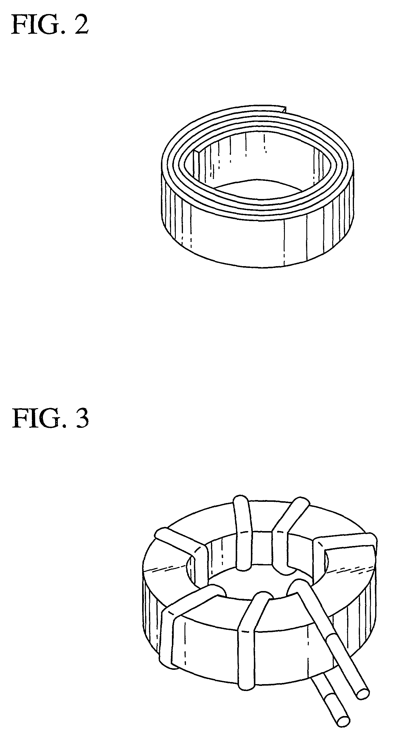
[0048] Each melt having respective chemical composition shown in Table 1 was formed into a ribbon of 5 mm in width and 20 .mu.m in thickness. The X-ray diffraction and the transmission electron photomicrograph of each ribbon showed that the resulting ribbon was substantially amorphous.

[0049] Next, the amorphous ribbon was formed into a toroidal wound ribbon while applying a tension in the length direction of the ribbon. The tension and the thickness tolerance of the wound ribbon are shown in Table 1.

[0050] The toroidal wound ribbon was then subjected to heat treatment in nitrogen atmosphere while applying a magnetic field of 200 A / m in the direction of magnetic path of the wound ribbon. Specifically the toroidal wound ribbon was heated from room temperature to 470.degree. C. over 1 hour and kept at 470.degree. C. for 30 minutes. Then, the temperature was raised from 470.degree. C. to a temperature shown in Table 1 over 30 minutes and kept there for one hour to crystallize the amorph...

example 2

[0060] The control performance, the temperature rise and the reset current at no load were measured in the same manner as above except for changing the switching frequency to 100 kHz.

5 TABLE 5 Temperature Rise .DELTA.T (.degree. C.) Reset Number of Control Maximum Current No. Turns Performance No Load Load (mA) Invention 1 7 good 24 34 45 2 7 good 23 33 43 3 7 good 29 39 52 4 7 good 25 35 46 5 7 good 28 39 56 6 7 good 19 31 36 Comparison 7 7 good 32 43 55 8 7 poor 20 31 34 9 7 poor 22 32 32 10 7 good 39 51 77 11 7 poor 20 31 33 12 7 good 39 49 75 13 7 poor 16 28 24 14 8 good 19 53 34 15 -- -- -- -- -- 16 8 good 16 43 46 17 8 good 11 41 21 18 -- -- -- -- -- 19 9 poor 37 69 78

[0061] As seen from Table 5, any of the comparative saturable reactors (Nos. 7-19) showed a poor control performance and / or a high temperature rise. In particular, the measurements were not practicable in Nos. 15 and 18 due to extreme temperature rise. Therefore, the size of the core used in the comparative satur...

example 3

[0063] The control performance, the temperature rise and the reset current at no load were measured in the same manner as above except for changing the switching frequency to 150 kHz.

6 TABLE 6 Temperature Rise .DELTA.T (.degree. C.) Reset Number of Control Maximum Current No. Turns Performance No Load Load (mA) Invention 1 5 good 28 35 87 2 5 good 27 35 82 3 5 good 32 39 94 4 5 good 28 36 88 5 5 good 31 39 97 6 5 good 22 32 69 Comparison 7 5 good 38 46 108 8 5 poor 24 31 65 9 5 poor 27 35 61 10 6 good 39 56 121 11 5 poor 23 32 63 12 6 good 38 56 119 13 5 poor 19 30 47 14 6 good 23 43 54 15 -- -- -- -- -- 16 6 good 29 48 69 17 6 good 18 41 37 18 -- -- -- -- -- 19 9 poor 39 83 112

[0064] As seen from Table 6, any of the comparative saturable reactors (Nos. 7-19) showed a poor control performance and / or a high temperature rise. In particular, the measurements were not practicable in Nos. 15 and 18 due to extreme temperature rise. Therefore, the size of the core used in the comparative s...


PUM

PropertyMeasurementUnit
magnetic flux densityaaaaaaaaaa
particle sizeaaaaaaaaaa
magnetic flux densityaaaaaaaaaa

Abstract

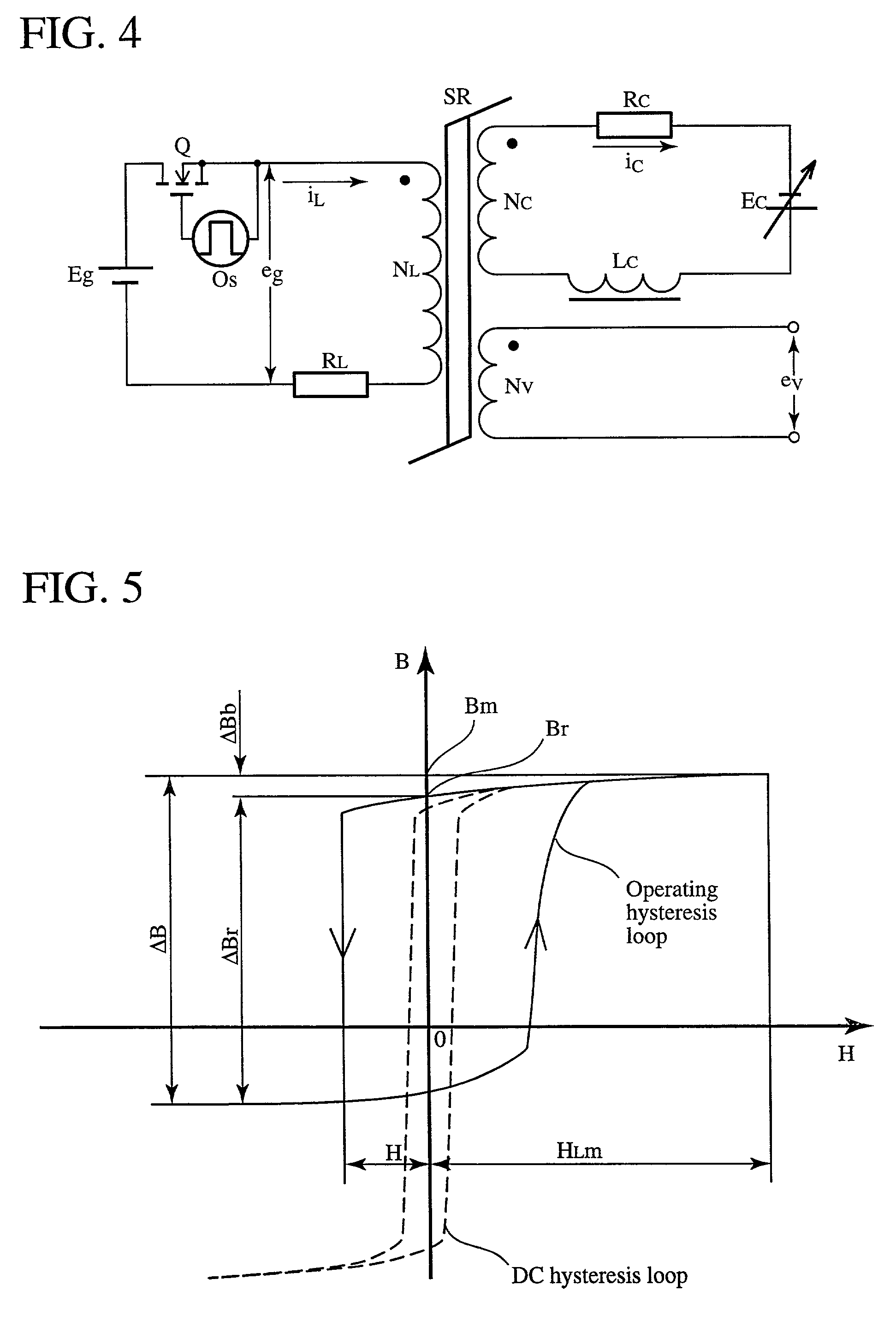
A magnetic core for use in a saturable reactor made of an Fe-based soft-magnetic alloy comprising as essential alloying elements Fe, Cu and M, wherein M is at least one element selected from the group consisting of Nb, W, Ta, Zr, Hf, Ti and Mo, and having an alloy structure at least 50% in area ratio of which being fine crystalline particles having an average particle size of 100 nm or less. The magnetic core has control magnetizing properties of a residual operating magnetic flux density .DELTA.Bb of 0.12 T or less, a total control operating magnetic flux density .DELTA.Br of 2.0 T or more, and a total control gain Gr of 0.10-0.20 T / (A / m) calculated by the equation: Gr=0.8.times.(.DELTA.Br-.DE- LTA.Bb) / Hr, wherein Hr is a total control magnetizing force defined as a control magnetizing force corresponding to 0.8.times.(.DELTA.Br-.DELTA.Bb- )+.DELTA.Bb.

Description

BACKGROUND OF THE INVENTION[0001] The present invention relates to a magnetic core for use in a saturable reactor, a multi-output switching regulator controlling the output voltage by a magnetic amplifier, and a computer equipped with such a multi-output switching regulator.[0002] The multi-output switching regulator has been used in personal computers and office computers. For example, in a PC AT-X type computer, a most typical desktop personal computer, a multi-output switching regulator with five outputs, i.e., +5V output (1.5-20 A), +3.3V output (0-20 A), +12V output (0.2-8 A), -5V output (0-0.3 A) and -12V output (0-0.4 A) is used when a larger output capacity is required. In the above five-output switching regulator, the main circuit comprises a forward converter with single switching element or a half bridge converter. The main output (+5V output) is controlled by a pulse-width modulation of a switching element located in a primary side of a main transformer, and the secondar...

Claims


Application Information

Patent Timeline
Patent Type & Authority Applications(United States)
IPC IPC(8): H01F1/153H01F29/14H01F27/24H02M3/28
CPCH01F1/15308H01F2029/143H01F27/24G06F1/26
Inventor NAKAJIMA, SHINMIKI, HIROHIKOKUBOTA, SADAMISAKAGUCHI, MUTSUHITO
Owner HITACHI METALS LTD
Learn More